
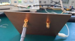
A phone call recently reminded me about some experiments a long time back, using some tunnel diodes to generate fast edges. Various circuits were built at the time, this is one of the final working versions. All soldered to just a piece of double-sided circuit board with two SMA connectors fitted.
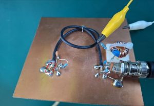
The trigger signal, a reasonably fast square signal is provided through the BNC connector. The bias circuit is separated from the tunnel diode by a few nanoseconds of delay line, which helps to make the transition stable.
From these “old days” I still keep many tunnel diodes that were at that time ubiquitous from the left-overs of even older soviet times (made in the late 1970). There must have been several boxes of tunnel diodes that made it to the Western market. Maybe from some surplus military sale or give-away, because many of the diodes are “military grade”.
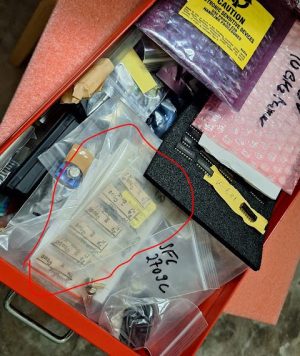
The diodes are for various currents, like, 5 mA and 10 mA, and there are both GaAs and Ge (germanium) types. For this circuit, I have the 1i305B mounted, a 10 mA fast-switching optimized Ge tunnel diode.
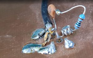
With a bias of about 8 volts, roughly 8 mA of current, I get the circuit to trigger nicely. At the BNC input, there is a protection circuit (a DC block and a 1N4148 diode to limit the amplitude). Tunnel diodes are susceptible to soldering heat, so be careful and use pliers to conduct away the heat from the terminals while soldering. I solder them “from the side of the board”, melting the solder on the board or connecting part, and then barely dipping in the pre-soldered terminal of the tunnel diode for merely a fraction of second, then cooling it with my finger. Slight burns may result but the diode will be safe.
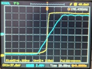
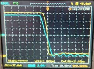
The rise and fall times are nice, the triggering is stable and precise. I have sold all my super-fast oscilloscopes (used to own a HP 54750a 20 GHz scope and a even a 54720a 1 GHz real-time scope, but sold these several years ago after completion of certain projects that required these – I don’t want to start a museum of test equipment so I regularly sell equipment that is no longer needed, especially equipment that is expensive and prone to degradation).
For the tunnel diode, there is even a datasheet available, albeit in Russian.
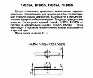
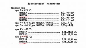
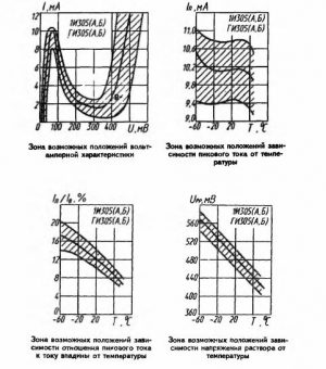
Easy enough to read with Google Translate, but even without translation, the key properties are obvious: peak and valley current, current ratio, capacitance. Over the years I have used some of these tunnel diodes to repair old oscilloscopes and trigger circuits. Typically, to substitute diodes that are no longer available (certain types of General Electrics) or otherwise prohibitively expensive. So far, never any trouble finding a suitable Russian diode.
![]()
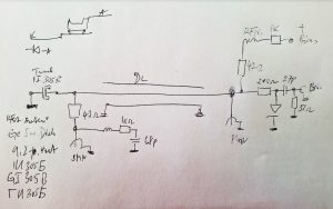
A quick schematic from the archives, sorry it is not written very clearly, but already more than 10 years old. Left SMA is the output – there is a 47 Ohms series resistor, and a small network at the outlet to suppress ringing. The delay line is just a piece of regular RG 174 (50 Ohm) cable.
There are also datasheets for a variety of other tunnel diodes available in the Manuals’ archive, contact me in case you can’t find them.