Category Archives: Miscellaneous

Mid-Autumn Festival: Moon Cakes

Whenever possible, I use the opportunity for a little celebration – this time, the mid-autumn festival, which is a national holiday in China. It is associated with the moon calendar and the autumn full moon, thus, its exact date changes from year to year.

Traditionally, moon cakes are served during the celebrations. This year, I wanted to try making some moon cakes with a filling that is more to my taste than the traditional egg yolk version.

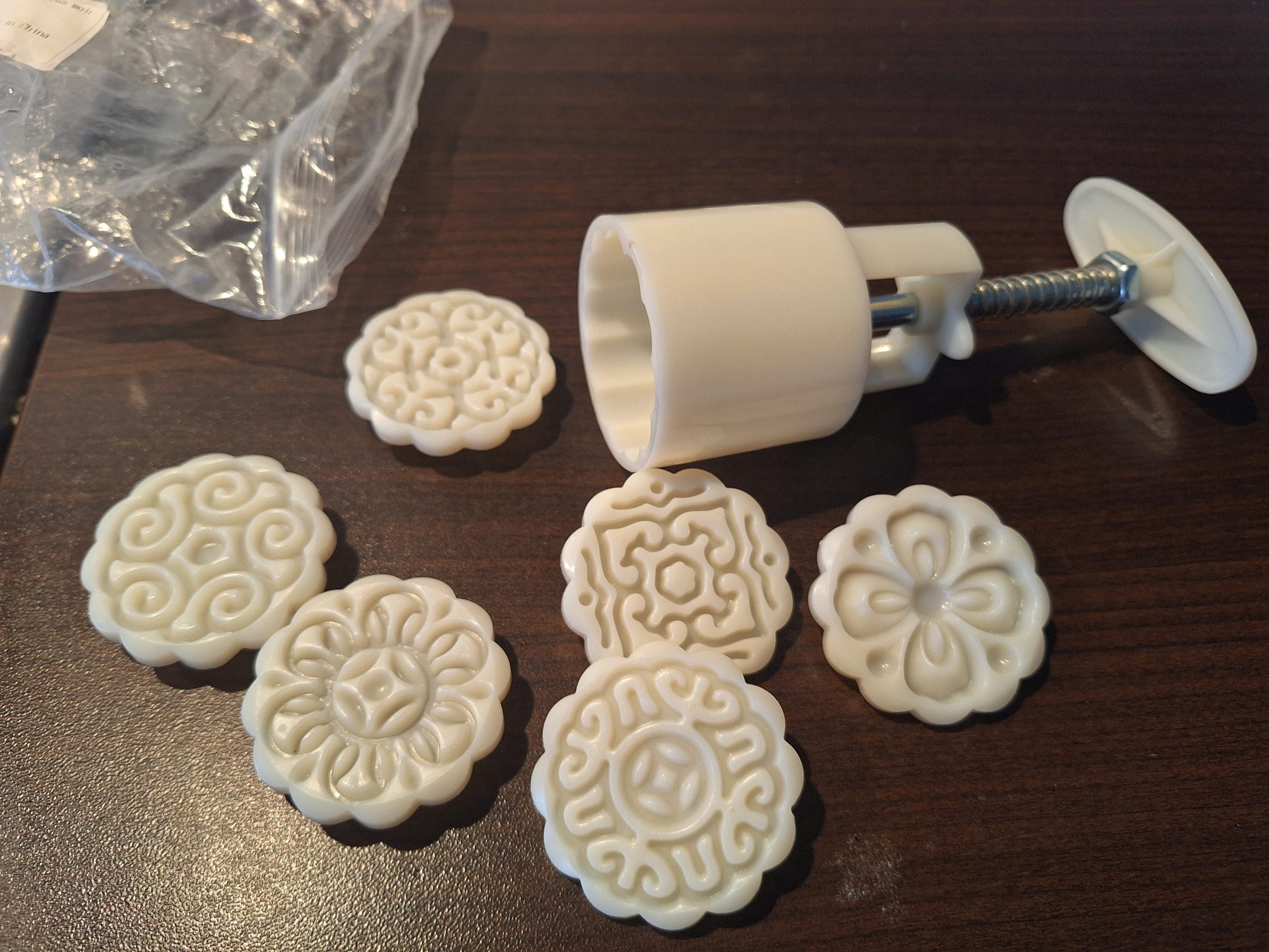
First, we need to get some special tool, a moon cake former. These come in various sizes, I use a “50 g” size.

The recipe is not that secret: the dough is made from flour, sugar sirup, some alkaline water and vegetable oil.
The filling-to-dough ratio recommended is about 6:4.
Say, for about 20 moon cakes:
230 g of flour (all purpose unbleached wheat flour), 145 g of sugar sirup, 55 g of plain oil, 1 tablespoon of alkaline water (saturated solution of sodium bicarbonate).
The dough needs to mixed and kneaded properly, then store it in the fridge for a few hours.

For the fillings I used two kinds.
“Date and almond”
170 g of chopped dates (without seeds!) -needs to be very finely chopped in a food processor
65 g of ground almonds
about 20 g of honey

“Poppy seed and almond”
250 g of poppy seed cake filling mix (“Mohn fix”, “Mohn back”)
135 g of ground almonds
Mix throughly.

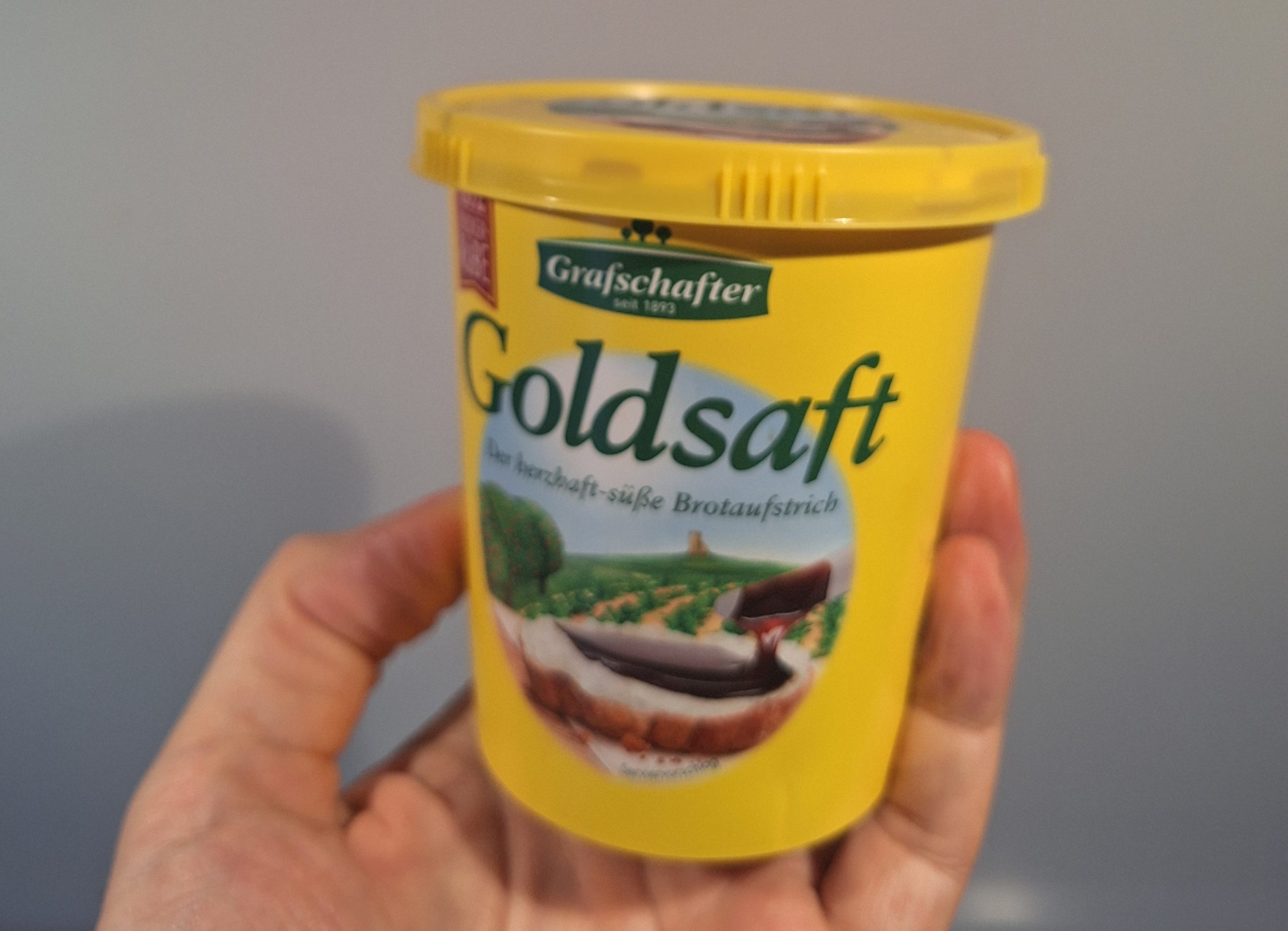
Some recipes call for certain Chinese sugar sirups, and these can be used if available. Also artificially inverted sugar can be used – I decided to use a more natural source, the so-called “Goldsaft” made from sugar beets. This will result in a little darker color of the cakes.

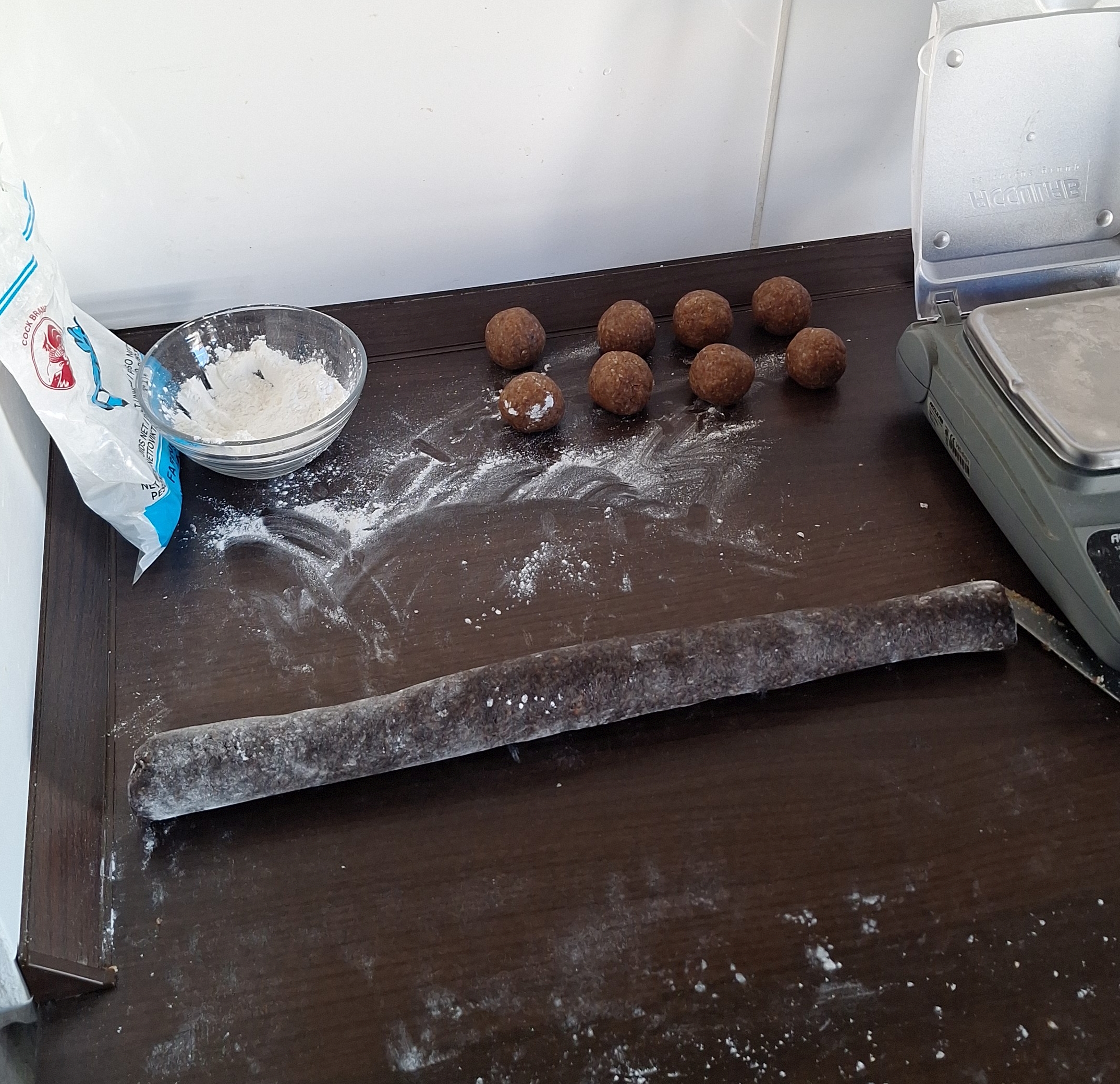
The dough and fillings must be precisely measured. I used a balance to ensure the correct weight.

The dough is first made into little balls, then rolled flat and the filling – also formed to balls – is wrapped in the thin dough. All is rolled by hand to a ball. Then, inserted into the former, and pushed in shape on a baking tray covered with non-stick paper.

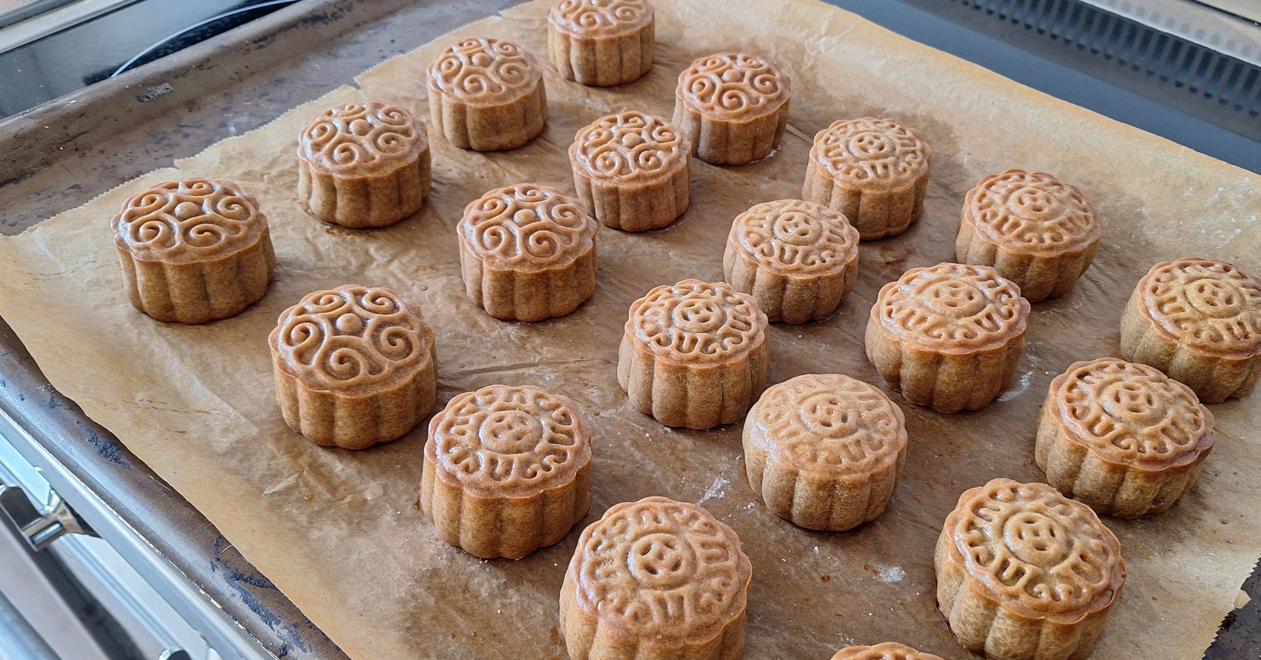
Bake about 9 minutes at 190°C, then let it cool down a little, say, 4 minutes, and brush with diluted egg yolk (I carefully mixed it and put it through a strainer to remove any lumps). Dilute with cold water in about 1:1 ratio and brush evenly. Then bake again for about 10 minutes. Watch carefully until the edges are a little brown.

Eventually, let them rest in a closed box in the fridge for a few days. But some, you may eat directly…

Afterwards, enjoy the evening with moon cakes and moon observation.

Adapting to hot summers: a new lawn

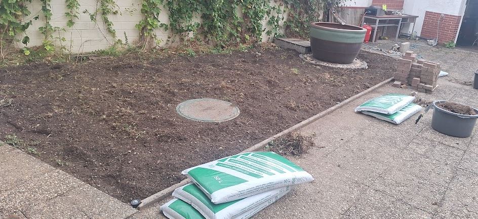
Between my house and workshop, the is a small green area, a lawn with an outdoor bath. Last summer already, with temperatures reaching 40°C, this lawn had suffered a lot, but this year, at 42°C, and two weeks of extreme heat, it didn’t survive. Asking around, neighbors had good success with installation of irrigation systems, and as I would rather adapt to hotter summers than suffering from the view of dry lawn, I decided to take the necessary steps.
With barely 25 m2, I first thought it would be an easy job, but as it turned out, more work than expected.

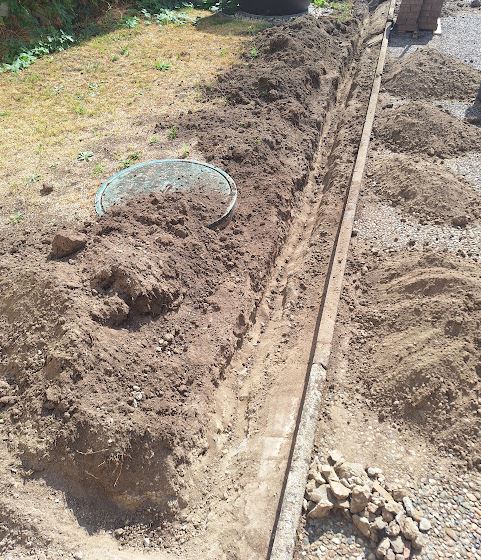
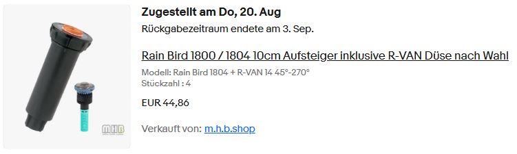
After some planning, the first step was to dig up the soil, and install the watering system. I had checked the sprinklers recommended by the neighbor, so-called Rainbird sprinklers that have a solid reputation. With all the effort of installation, I don’t want to take chances that the sprinklers will fail.

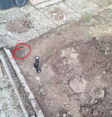
Digging down, there were many troubles discovered. At the locations where the sprinklers need to be put (at the perimeter), concrete. Also in the soil, after about 8 cm, lots of stones and other hard material. The top soil, rather sandy.

With heavy tools and big drills, finally the concrete obstacles gave in. Time to order the Rainbirds.

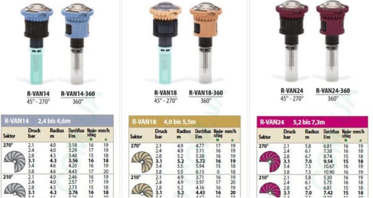
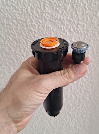
There are various nozzles, I selected the R-VAN14 nozzle, which seems appropriate for the distances. Maybe one I could replace with a little further range R-VAN18 nozzle eventually to reach into the distant corner.

These R-VAN nozzles have multiple jets rather than fine mist, and the droplets nicely water the lawn.

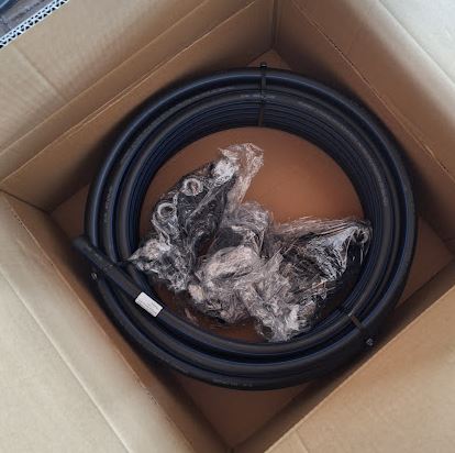
For the piping, I installed fully pressure rated DN25 cold water PE pipe. These are very stable and not affected by stones and similar.

After some waiting, also the Rainbirds arrived, time to proceed with installation.

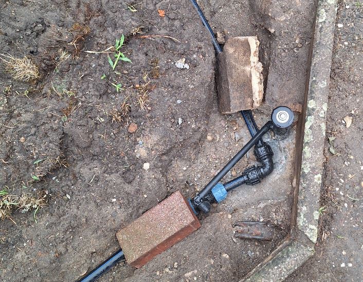
To connect to the main pipe, I used 1/2″ inner thread pipe T fittings and 1/2″ outer thread flexible connections.

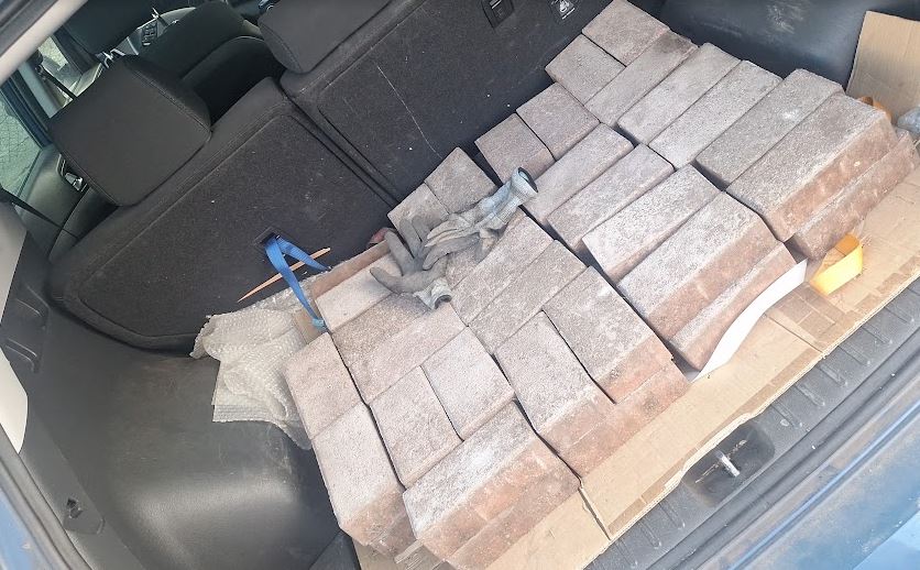
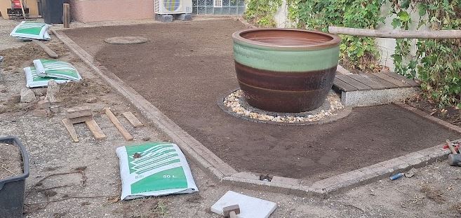
After all the drilling and preparation, the installation went smoothly. To provide a boards, and easier cutting later, I got some used paving stones that matched exactly the type used in other parts of my garden. A friendly guy from the neighboring town had them advertised in the classifieds as “free to pick up”.

To prepare the soil, I first used an electric tiller to chop up the leftover grass and stones and hard topsoil (mostly sand and small stones). All the old grass removed and all stones large than about 1/2″ removed. Used a wooden board to make sure all is precisely flat. From what I learned, it is imperative to level the area precisely, don’t do a sloppy job.

After some repeated leveling and adjustments, removal of all roots, stones, etc. — very tedious work — I was happy to only deal with the 25 m2 here.

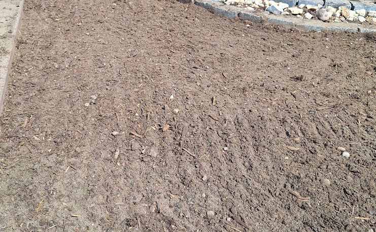
Added about 250 L of compost soil (about a large bucket per m2), not a lot, but enough to provide some organic structure to the sand soil.

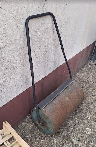
Spreading the compost evenly, more leveling. Finally used a heavy roller that more distant neighbor kindly borrowed me.

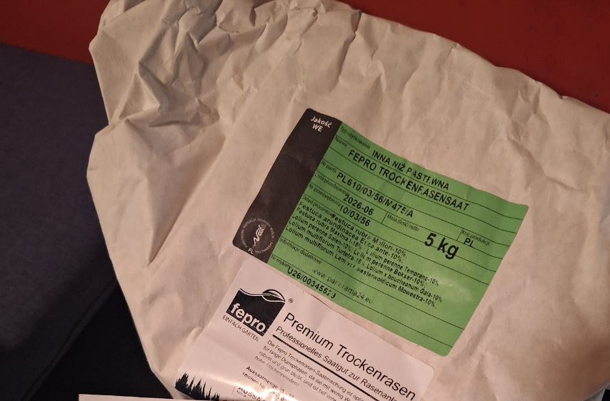
For the grass seeds, I decided on a dry-resistant mixture, but not a hard “desert grass” or similar hardy variety.

The 5 kg are certainly too much, but the often claimed 25 g/m2 needed seemed not quite enough. I added at least 50 g/m2, and more around the (many) corners, edges and other difficult areas.

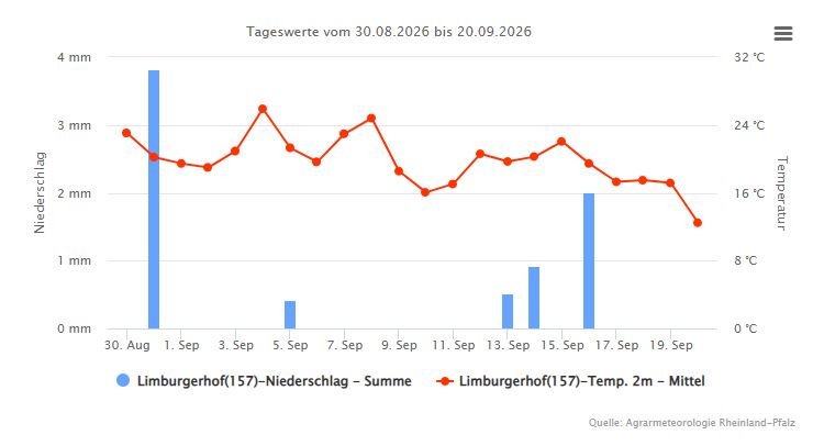
Anxiously watching the weather forecast, a very nice period without heavy rain came up, and eventually, the weather turned out very good. Strong rain in the first days is definitely not good, it will wash away the seeds. Also great heat must be avoided, the fresh grass needs to be moist at all times.

Cold weather below 10°C (at night) is also not good to start a new lawn.

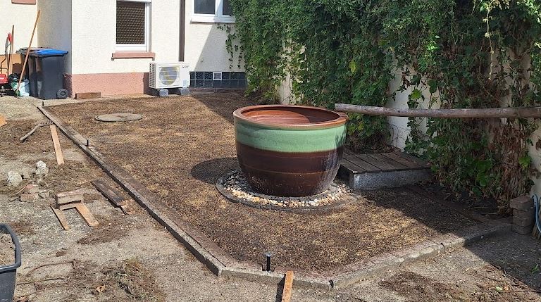
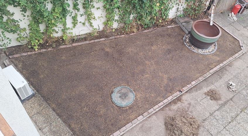
Finally, roughened the surface of the leveled soil, and added seeds by hand as uniformly as possible.

Gently rolling it on the (rather dry) soil with the heavy roller to ensure good soil contact of the seeds.

A few days later all is moist, and the sprinklers on twice a day for 15 minutes.

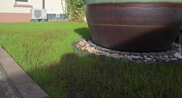
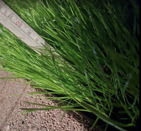
To my great surprise, already after 4 days, we can see the grass grow.

…more and more, faster than expected.

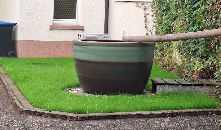
after 2 weeks:

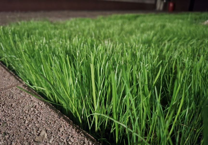
When grown to about 15 cm, for the longest leaves, I did some test to check the roots. These seemed fairly firm and well-developed. So I sharpened the blades and tried a first cut.

Certainly recommended to do a light cut, and to avoid pulling and turning the mower on the fragile soil and fresh gras.

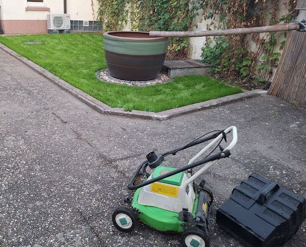
I cut the grass to 8 cm, and collected all the cuts carefully.

It is such a pleasure and delight to see the lawn green and growing nicely. Will continue to cut it about once a week, depending on weather and growth.

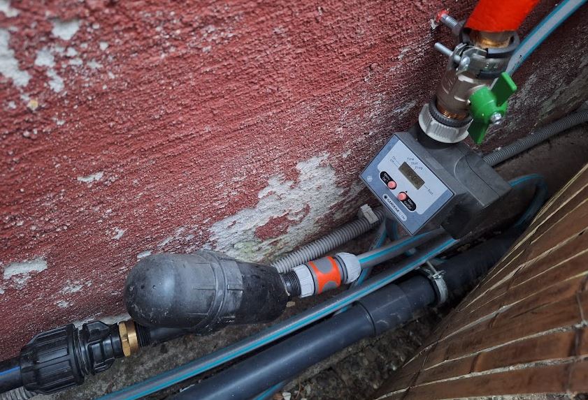
The watering is controlled by a simply Gardena C14e watering controller I still had laying around. The output connects by short hose, with quick connects, to a filter (100 µm nylon filter), which is connected to the DN25 water pipe. It is all water from my own well, so I had to extend the well water pipework a little (using Pipetec 16×2 composite tubing).

All in all, with the disposal of the waste, the side tasks related to well water, the drilling, concrete repairs, soil treatment, stones – quite a big effort but so glad it seems to pay off already!

Antique Weights: return to scale

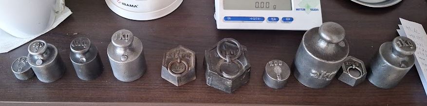
Recently there is lots of work around antique balances and weights to support a collector of these items, and recently a very unusual package showed up at my workshop, a set of old weights for restoration. Basic intention was to remove all grime and dirt by bead blasting, but surely we need to check if the weights are actually usable.

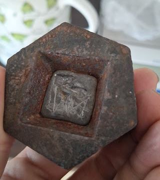
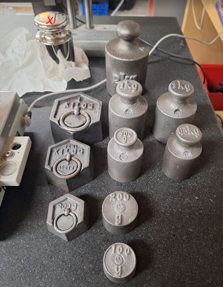
Some were of the traditional knob style, while others have a hexagonal shape and are adjusted with lead at the bottom.

Unfortunately, except one that was heavy (with a lot of dirt on it), all were light. So we have to find a way to add mass to these pieces. Unfortunately, I couldn’t find any instructions how to do this, because all the modern weights cavities closed with screws or a plug of lead that can be hammered in, but these old-fashioned weights are lacking this feature. For the hexagonal weights, it is clear that we have to heat them and add more lead, but for the knob weights, let’s hope there is enough space inside to fit material for adjustment.

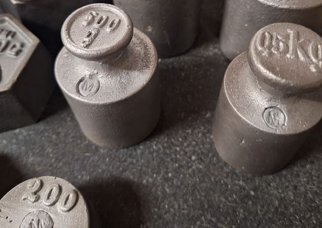
All the matters of weights are regulated in the OIML R111 rule: it says that adjustments must be made on this class of weights (“M” is the class for the not-so-accurate weights used for general trade and general use).

The adjustments should be made with heavy metallic material, like lead shot. After drilling open the lead caps of the old weights, and removing the remaining pieces with a screwdriver (it is enough to drill an approx. 6 mm hole and then remove the remaining material by a chisel or screwdriver – avoiding to drill into the cast iron ruining drills and taking time.

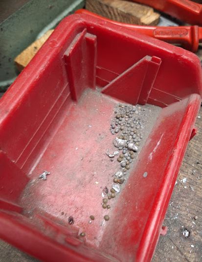
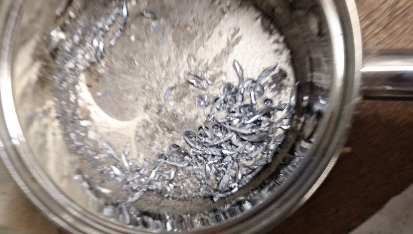
What I found inside was indeed some lead shot, but also dirt and sand and other lead pieces. I didn’t clean out all the weights but simply added some old lead fragments to get the weight up to the required range. This has to be done while accounting for the mass of the lead plug. This plug will take about 5 g of lead for the 500 g weights, about 7-8 g for the 1 kg and 2 kg weights.

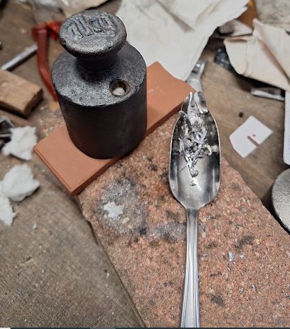
Various methods may exist to close the lead plug, by I found it the easiest way to first insert a little bit of glass wool and then pouring molten lead from an old spoon, heated over a gas flame.

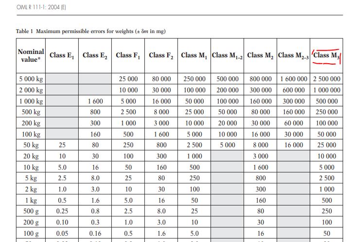
Best method seems to be to target a final weight a little, say 0.2-0.5 g above the target – closer if you have some practice. The allowable tolerances for M3 class weights – that’s the target I am following can be found in below table. Still my objective was to adjust these to +-0.01 g as much as possible by cutting away some lead from the plug after letting everything cool down.

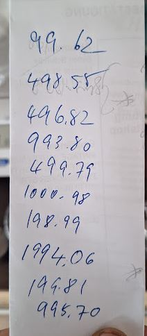
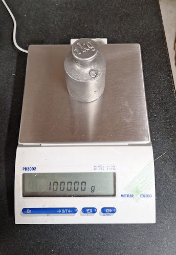
For the adjustment I used my good Mettler PB3002 balance, 3000 g capacity with 0.01 g resolution. Set up on my surface plate and calibrated with a 2 kg F1 class weights (+-10 mg at most). Also cross-checked the linearity at 500 g and couldn’t see any deviation (measuring as 500.00 g).

It is a little tedious to adjust all the weights but eventually all the pieces were done, and I also fixed some old weights I had for a long time (which were also light because of metal loss from severe rusting). Before the fine adjustment, the pieces were all glass bead blasted and thoroughly cleaned.

Finally, all the weights are done and double-checked. Frequently also put the 2 kg F calibration weight (upper left) to check for any drift, which was found to be absent. FOr the smaller weights, I used my analytical balance – the 100 g weight turned out to be exactly 100.0002 g, lucky!

I can’t really stamp an official mark on these, so I used a letter “M” both to firmly compress the lead plug and to indicate the accuracy class of the weight. Supposedly, these weights will be handled in a kitchen so I made the lead plugs almost flat with the surface, rather than protruding, to avoid hand contact with lead. But by adjusting the lead quantity, it is easily adjustable.

Christmas Bakers: Dominosteine – dominostones

This year a good friend has been asking me to prepare “Dominostones” together. It is a kind of German special Christmas cookie, which is normally purchased at supermarkets because fast machines can make these things much more accurately and faster than human had. However, always up for a challenge. Handmade goods of such rare nature will also be a handy gift.

First, we have to make a thin dough base.
120 g of honey (cheap honey is OK)
30 g of sugar
1 tablespoon of mixed spices (cinnamon, etc., use gingerbread spice)
100 g of wheat flour
100 g of heavy rye flour
1 egg
3 g of ammonium bicarbonate (“Hirschhornsalz”) dissolved in some warm water (10 ml)
3 g of potassium carbonate (“Pottasche”) (dissolved in a little it of warm water)

Warm up the honey a little in the microwave to make it liquid, dissolve the sugar in it. Some little remaining sugar is no problem. Add a mixture of the flour and spices (best, pre-mix as dry powder), add the egg. Add at one side the dissolved ammonium bicarbonate, mix a little, add the potassium carbonate solution at the opposite site (don’t mix these two things together).
Let the dough rest for a few hours (wrap it tightly with cling wrap; not too cold, say, 15-20°C).

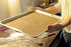
Use a good pan with some anti-stick paper, be sure to roll it to a uniform layer. The size of my pan is 43×32 cm. Similar size will also work.

Bake approximate 8-10 minutes at 200°C (upper/lower heat; air convection oven you may try 180°C).

Let it cool down.

Take about 600 g of apricot jam (screen it through a mesh to remove any solids), add 150 g of water with about 9 g of agar-agar (a pale powder). Boil for 2 minutes. Let it cool down with occasional stirring, but don’t let it get firm. Apply to the dough base in one go. First leave a little distance (say, 0.5 cm) to the edge, then apply more and more ensuring that it doesn’t flow down. If to liquid, wait a little, however, it is best to apply all in one operation, to avoid forming layers of gel that can later separate.

After some cooling, apply a marzipan layer.

400 g of marzipan (baking marzipan)
150 g of powdered sugar (not icing sugar or similar mixed products, must be 100% pure powdered sugar)
Kneed the marzipan and sugar to a uniform mass by hand. This takes some effort. First work in 1/3 portions, then combine all together. First, it looks as if it cannot mix, but after a while, it will. Roll this material to a thin layer large enough to cover the full pan. Use small quantities of flour to prevent sticking.

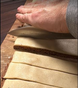
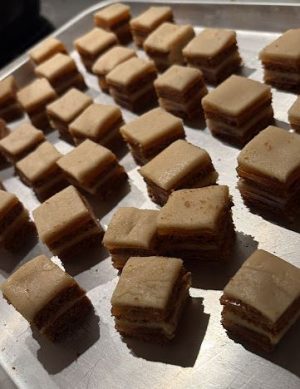
Cut the combined layers. I like to double-stack them: dough-gelly-marzipan-dough-gelly-marzipan. It is recommended to make so nice bite size pieces, not too small. It is an item served in single-piece quantities.

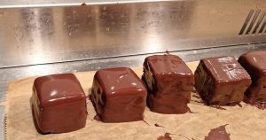
Cover with chocolate, by dipping them first, piece by piece, in chocolate and removing excess chocolate with a wood stick or similar tool. It is important to liquify the chocolate glaze in water bath, don’t overheat it.
About 400 g of chocolate (dark is preferred) will be needed.

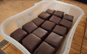
Finally, put them in a box for safe storage. Otherwise, they may get eaten faster than you believe. Better to store at about 15-18°C, constant temperature. Don’t put in the fridge.

A Garden Pump: a surprising level of complexity

Now, after winter has ended and frosts are no longer severe enough to endanger my outdoor water system, time to restart the pumping system. For garden watering and general outdoor water needs I operate a small well, including an automatic pump, but during winter time, this is shut down and the pipes all emptied to protect the pipework and pump from freezing.

Normally, just a task of a few minutes to start the pump after filling it with water, but this time, no success. No water, no suction. Checked the well – plenty of water there. Also the pipework is all good and sound.

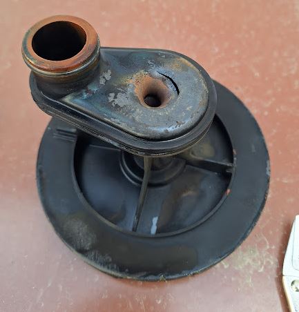
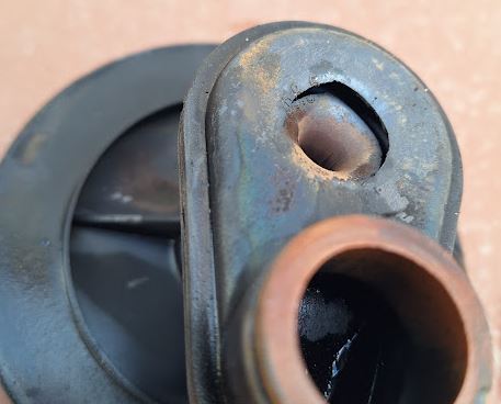
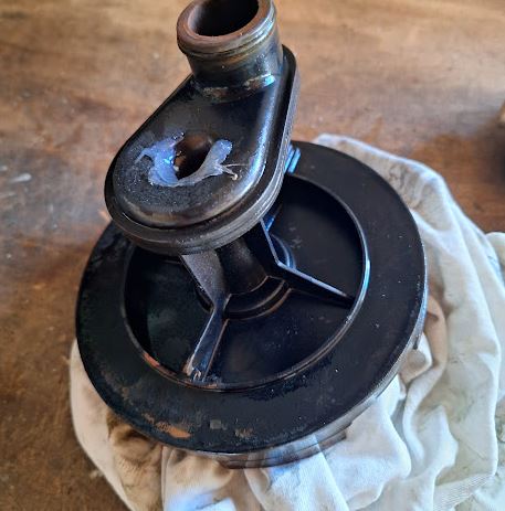
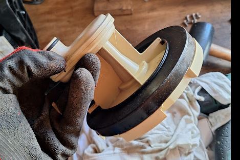
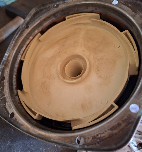
After some searching hear and there, I decided to open to pump and found a very unexpected defect – one of the critical inner parts, the so-called ejector which is needed to prime the pump (by removing air from the system) had a crack. Probably because of fatigue of the plastic material.

This part uses the water circulating inside the pump to essentially pump air out of the suction pipe going to the well. With the crack, it can’t effectively evacuate the suction pipe, thus, no water can be pumped.

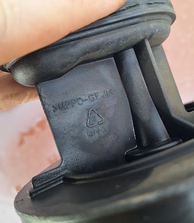
The plastic material is good, a special form-stable and durable hard plastic, reinforced with glass fiber. Maybe a low-quality material batch, or some design flaw?

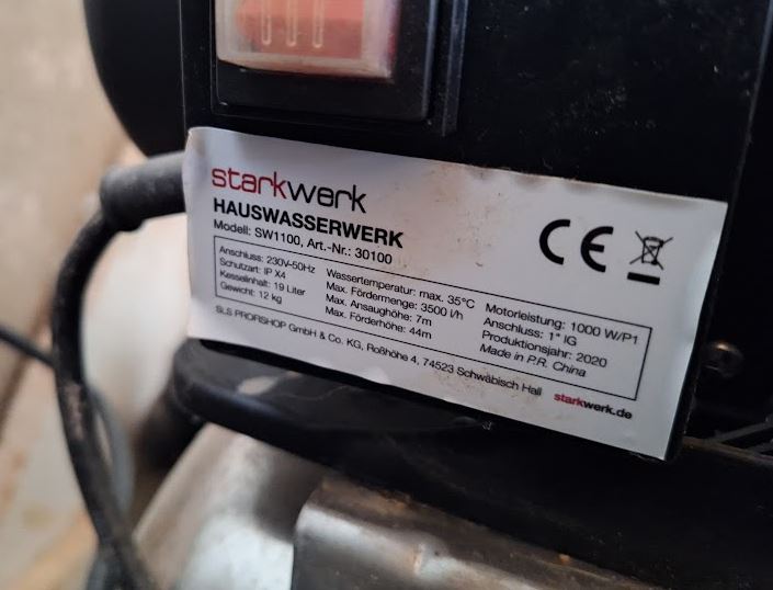
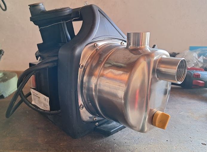
The pump, purchased in late-2020, is of the brand “Stahlwerk”. It was not expensive at the time, just about 100 EUR at the time of purchase, stainless version, including a small buffer tank and pressure control system. Anyway, the price is good, but the quality of the “Stahlwerk” goods, you judge yourself! Shouldn’t a garden pump last more than just three summers?

To check if the crack really is the root cause, I sealed it with some hot glue, and despite the deviating geometry of the ejector nozzle, the pump worked right away.

But such temporary repair is no good solution for my garden water system, which requires automatic, unattended and reliable operation all through summer. So I checked “kleinanzeigen”=classifieds and found an almost new, barely used pump close-by, for a very reasonable price.

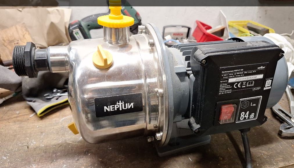
It is called “Neptun”, after the Roman god of the rivers and seas, hope he will be able to ensure the water flow to my garden for years to come.

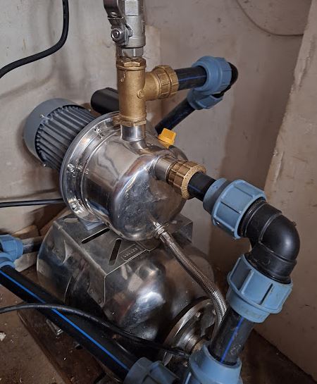
The pump, easily capable of 4.5 bars of pressure, stainless construction, and a solid 1 kW motor delivers very nice quantities of water, good pressure, and was easily installed on the existing buffer tank.

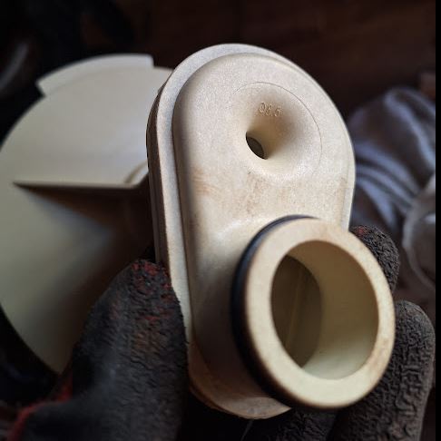
For the “Stahlwerk” pump, at least spare parts are available and the customer service was responsive. The spare part was reasonably prices, so I decided on a permanent repair – and after a few days got a new ejector insert delivered in a package.

Still made of the same polymer, but looks a bit heavier and the color has changed from black to white.

It matched nicely the dimensions of the old part. Cleaned all the old O-rings, and re-used these with no problem at all. Just take care when installing not to twist and of the O-rings, keep all nicely aligned and avoid undue force.

Now, while the Neptun will do the job, there is a spare “Stahlwerk” pump in the basement, just in case!

May the well never run dry!

Tool Grinding Machine Saacke UW II: many new copper nerves, and a new silicon brain

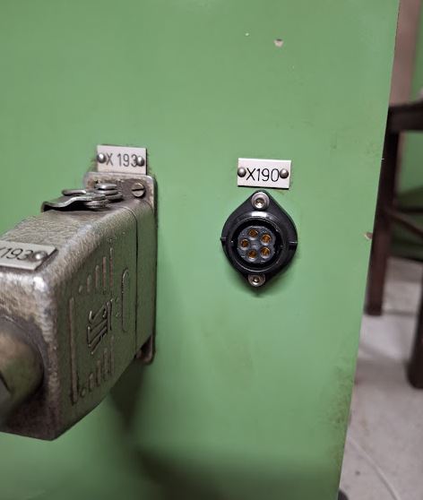
With the basic installation of the servo motors complete, still some work to connect all the motors and encoders solidly to the controllers inside the (massive) control cabinet. First, wiring the cables through the base of tool grinder, a heavy iron casting. This casting is made of a rather hard type of cast iron, difficult to drill larger holes by hand tools. So I tried to to re-use existing plugs and connectors as much as possible. While for the power connections, there are plenty contacts of the big industrial connectors and cabling available, for the encoders I wanted to use twisted pair cable and plugs that are physically separated from the power cable feed-throughs and plugs.

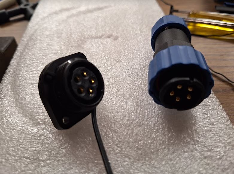
Shopping around, I found these Aliexpress plugs, from China, but with good IP rating, IP68. The cost is very moderate, and the size “SP20” happens to fit the openings and screws of the former fan power connectors.

Fortunately, these connectors arrived quickly and there was no need for any modification of the machine base.

To guide the cables of the encoders (total of 4 cables, 2 twisted pairs each), there was not enough space in the existing duct. So rather than wasting time with pulling heavy cables, I just decided to add another duct from the machine base to the control cabinet, dedicated to the encoder cables.

Installation was not easy – drilling a sizeable hole in the machine base took quite some effort, but eventually, the cast iron could not resist a sharp Cobalt-alloyed core drill.

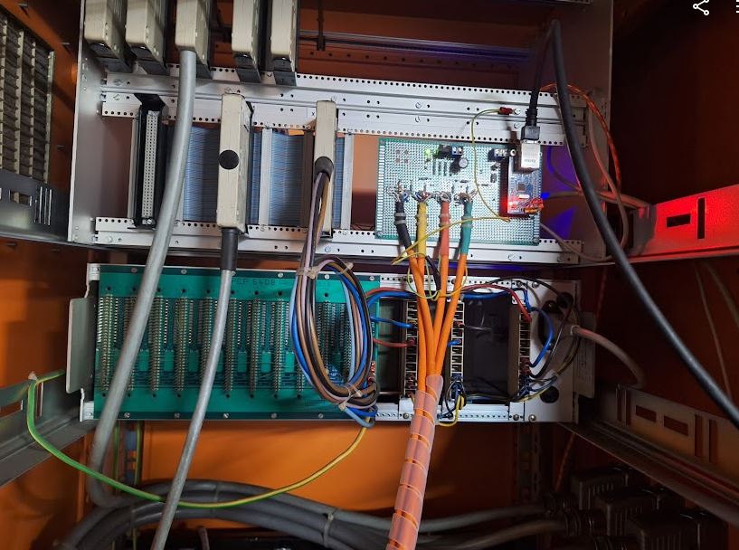
Next, some important work inside the control cabinet. After removing all the old controls and motor drivers, there is now ample space available, but all we will need is a 160×100 mm board, and even that is mostly needed to connect all the cables.

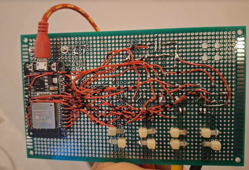
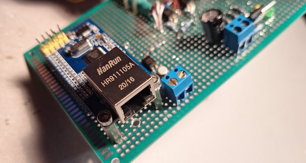
Key part is a ESP32 board, which does all the heavy work, on the other side, a W5500 ethernet interface, connected through SPI.

The soldering went faster than I thought, and the board is now mounted to the frame of the old control system. All powdered by a single 5 V power adapter (and an on-board 3.3 V regulator).

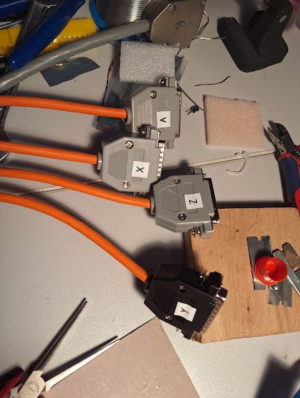
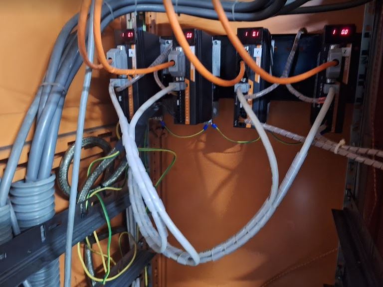
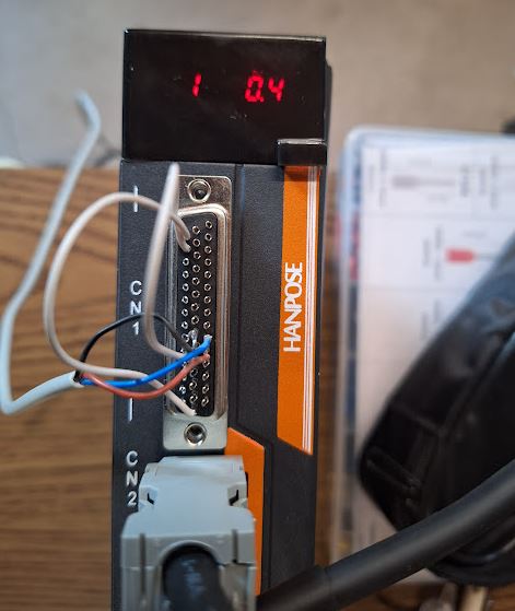
More time consuming that was all the other cabling, each of the controller has a 50 pin high density D-sub plug, with the fault, step and direction signals. I used some twisted pair (CAT) cable to make the short connections from the servo driver to the ESP controller.

At the driver side, it now all looks neat, and also the connectors of the encoders were cabled with IEEE1394 (SM-6P) standard. Lots of work with tiny wires, heat shrink tubing, etc.

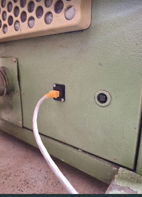
Finally, I mounted a CAT6 panelmount connector, so the whole grinding machine is now controlled by one ethernet cable, running UDP protocol.

Key part of this is the software, and while I have other machines running with (expensive and – in Europe – difficult to get) MESA cards, this time I resorted to a public domain development found on Githup. A really great project there. I managed to get some bugs removed and to make it work for my needs with 4 axis and one ESP32. The pin layout is quite critical, because the signals and the ethernet SPI will basically require almost all outputs of the ESP32.

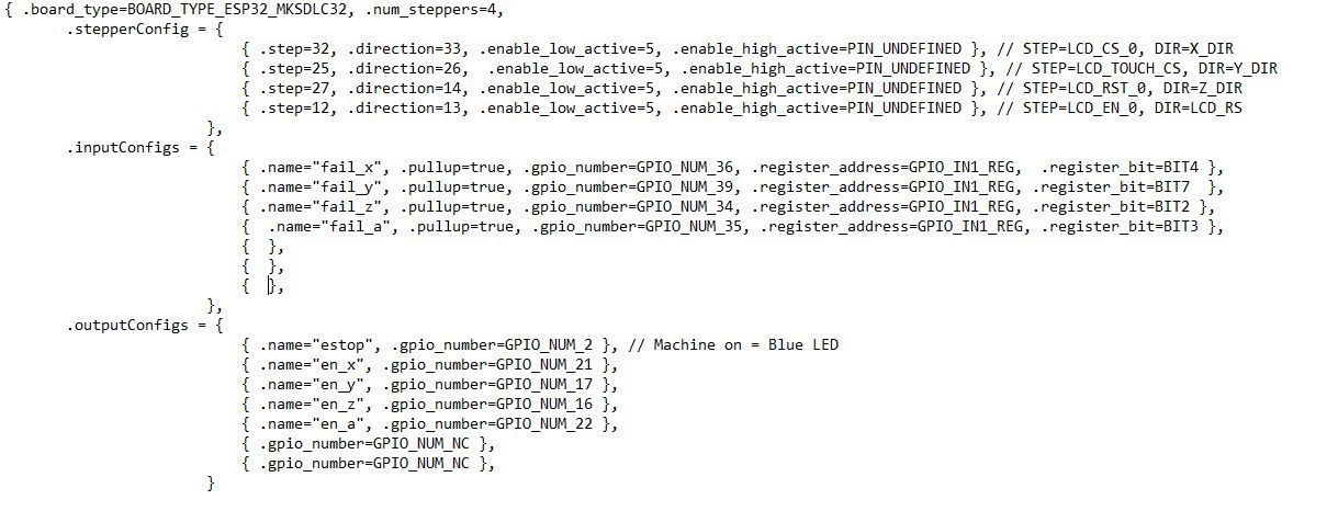
Some issue existed with the configuration, so I decided to hard-code the pins. Anyway, for now it is the only machine I have to control by this ESP32 motion control software, and there is no problem to customize it directly in the code.

For those interested in detail, here is the port layout.

As before, the motion control will happen through LinuxCNC, with a HAL driver that is talking to the ESP32 through UPD updating the motion commands every few milliseconds. All the step generation and time-critical motion control tasks are done directly in the ESP32, so the communication between the LinuxCNC and the ESP32 is not that time critical. I won’t describe all the driver tuning and LinuxCNC configuration here in detail. Drop me a line if you are interested. Probably I can get you started on some own projects.

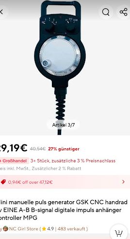
From Aliexpress, also another part arrived – a handwheel – rather low cost but good look and feel. This will be connected to a parallel port, because there is no time-critical events there, just reading the signals and linking them to a software quadrature encoder in the LinuxCNC HAL.

Tool Grinding Machine Saacke UW II: fitting new servos to the the old machine (A, X drivers)

For the X (ball screw driven left and right) and A (rotary) axes, now as the servo motors have arrived, we need to find a way to mount the servos to the existing drive mechanism. My intention is not to modify any of the shafts and precision parts of the Saacke machine, but to determine a way to mount the servos with high precision of axis alignment, and a coupling that can transmit the torque without slop or delay.

The mechanical parts and brackets, I decided to use aluminum alloy rather than steel, even Saacke manufactured the stepper motor mounting plate for the A axis from aluminum plate, and the strength will be good enough, with no need to paint or oil the necessary adapter plates.

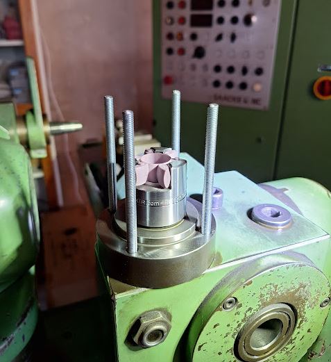
The couplings, I used KTR Rotex, size 19, with 92 Shore TPU elastomeric couplers. These were available already machines to the right size, including matching keyways. Found them used, or old stock, a good deal.

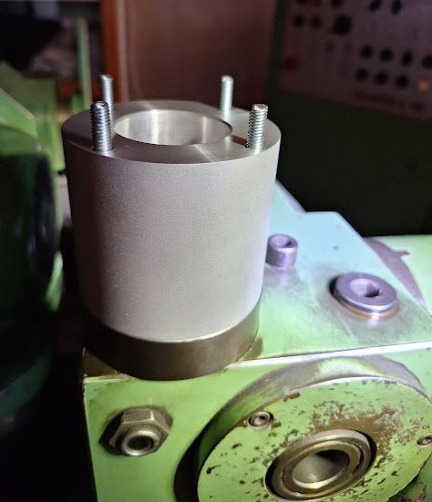
To house the coupling, made a cylinder from aluminum alloy, and 4 holes drilled for draw-bolts. The draw-bolts screw into the A-axis head, and nuts will be used in the servo mounting plate to hold things together.

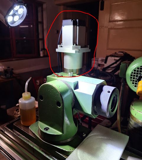
The servo mounting plate required quite some planning to match both the machine side, the servo flange, and the fan cover (which I plan to re-install to protect the servo – the cooling fan doesn’t seem to be required).

For the connection of the coupling and the head drive, made a rod with a long key slot (formerly, the long shaft of the stepper motor was directly fitting into the A axis drive head.

Fortunately, all the parts fit right away, torqued the draw-bolts carefully, and adjusted the couplings for proper clearance. There was a little slop in the coupling, so I bent some thin shim stock to pre-tension the polymer coupler a little more.

The distances and plate thickness was designed such that there is enough strength, without adding to much weight or unnecessary stick-out.

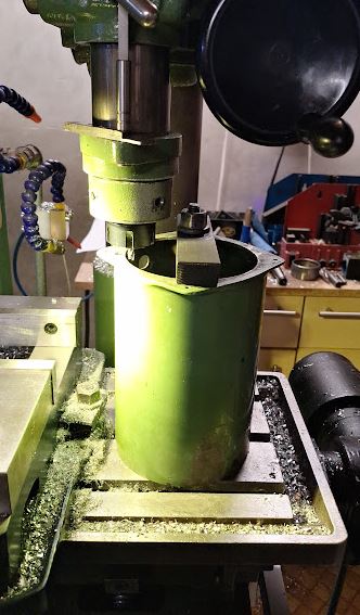
The fan cover, steel, had some other fans originally that you damaged during transport, and the adjustments for new fans were done by hand before, now a good chance to clean these (grit and dust filled) covers (there purpose was to direct the fan air around the stepper motors), and to mill out a little more space for the cables.

Handy to have the manual mill, and various workpiece holding.

With the cover mounted, all looks nice and neat, and overall a few kgs lighter compared to the former stepper motor. The cover is held in place by 4 screws, radially arranged, that have steel (stainless) spheres pushing onto the servo.

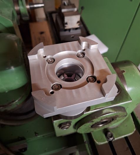
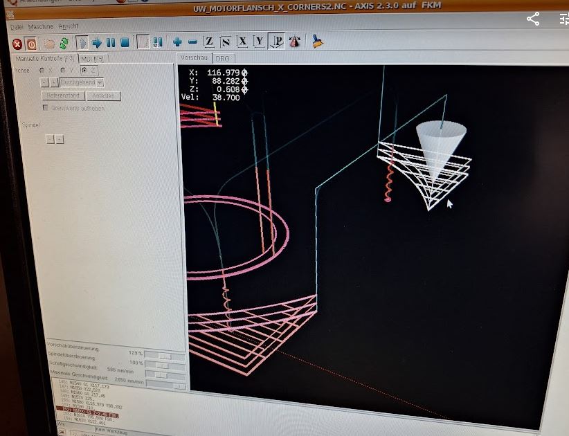
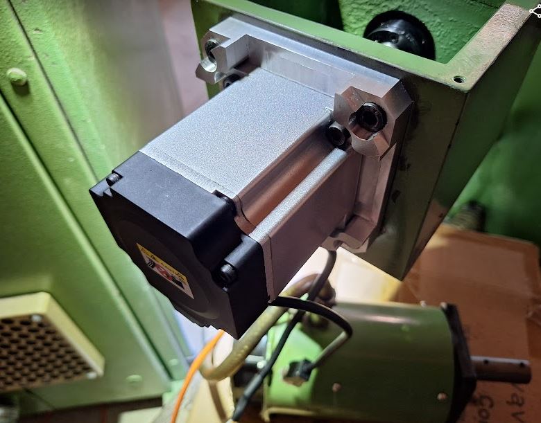
For the X axis, similar case, programming the CNC code, milling the aluminum plates. These mill jobs took a little while with some many features, but no purpose to optimize the program for a single piece.

There was no need to drill new holes, the plate was made such that the existing stepper motor threaded holes can be used.

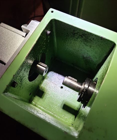
The spindles shaft and the servo shaft have different diameter and key size, but also here I was able to find suitable KTR Rotex couplings.

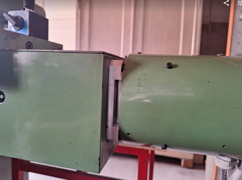
With the cover, it looks like not much has changed vs. the stepper motor, and there is still enough space for the cables (drive cable 3 poles plus ground and encoder cable – 2 twisted pair plus shield).

With all the work on the X axis, I used the chance to clean the screw bearing thoroughly, and adjusted the ball screw precisely (with a micrometer resolution dial on the table, and checking the pre-tension), but also found that the bellow cover is was badly worn, full of grease and dirt.

Finding a replacement bellow cover, from the original manufacturer, a German company, I was not even able to get a quotation, which would likely be cost-prohibitive anyway. Looking through Aliexpress, found a very cooperative supplier in China – this company provided a custom made cover for just about 30 EUR, shipping to Germany included (no customs to be paid). They were not able to provide small “tabs” at the side to hold the bellow cover in place, therefore I cut some from PVC plate, white color was the only thing I had available – but it will not be visible once installed anyway. Using special PVC glue, which really softens the plastic and welds it firmly, these plates were attached with very good strength. Also made a test piece, and could not actually break the glue joint without destroying the whole piece.

Installation of the bellow cover was easy – some small brackets and 3 screws each side, and the dimensions fit well. The material of the Chinese supplier seems pretty durable, oil and solvent resistant material, and many PVC frames (in each fold) to make it stiff and keeping shape. Let’s see how it will perform over the years.

Tool Grinding Machine Saacke UW II: steppers to servo motors

Some more work on the Saacke, the original design had 3 motor drivers for 4 stepper motors – the Y and Z axis being operated by one drive. My original plan was to get another stepper motor driver, but for these 6-phase high current steppers, not an easy thing. While there may be some old controls available, they are pricey, like 1000 EUR and more. Also, I was not too thrilled by every year repairing at least once the driver – 30+ year old electronics doesn’t normally provide a particularly high level of reliability.

Another choice would be to replace the RDM-51117 steppers with some other (2-phase) stepper motors, but rather than 1000 steps per revolution that would result in only 400 steps (half-steps) per revolution, or not very precise micro-stepping. Not good, because the Y and Z pitch is 1 and 3 mm/rev, respectively, and a grinder normally should be controllable in 1 mikron, or smaller, increments.

Analyzing the torque requirements, I had the idea to use a servo motor instead, because the holding toque requirement is actually pretty small (the feed screws turn easily, and once at position basically no force needed). AC servos (with an encoder feedback loop) have become affordable in recent years, why not use one of these?

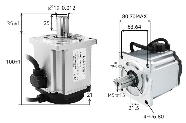
Shopping around at Aliexpress, I found these 80SS75 (750 W) AC servos, offered including drive and 3 meters of encoder and power cables. Available from a Chinese vendor (Hanpose), ready to ship from a Belgium warehouse.

Chatting with the sales manager a little, the lady offered my a very good deal, almost too good to be true – so rather than buying just one motor, I ended up ordering 4 sets, and decided to replace all the stepper motors by servos.

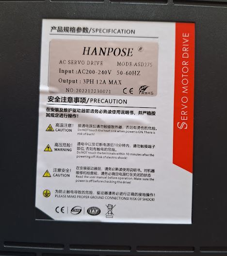
These servos come with ASD275 drivers, these are quite similar to other AC servo drivers I have used before, they all follow similar programming and characteristics. One important characteristic is that these drive need tuning of the control loop once installed.

Only a little wait, then 4 boxes arrived – all stuck together and wrapped in plastic, not bad!

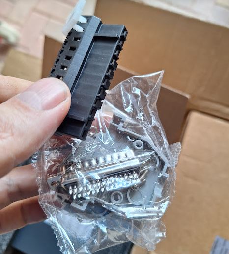
These sets include not just the cables but also the connectors, great! Full sets! Even an English manual is available.

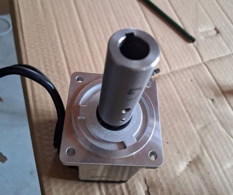
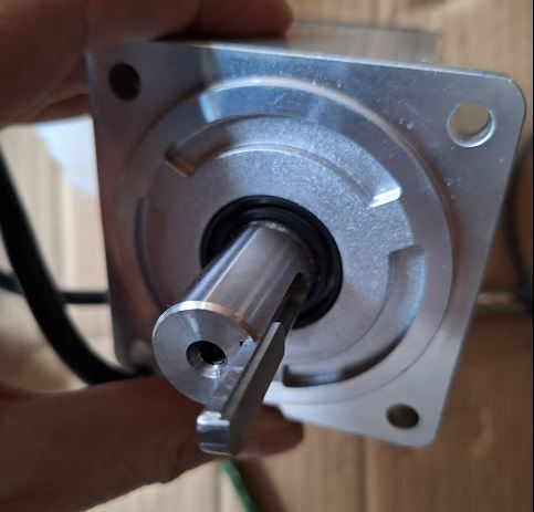
Some mechanical differences exist, so we have to make adapter plates, and modify the couplings. The Saacke design has just hard-coupled drives, there are no fancy parts, just a steel sleeve. This works well when all is centered up correctly.

Also the key had to be modified, because the sleeve has a 5 mm keyway, but the AC servos have 6 mm keys. So I milled away half a mm each side, to make it fit.

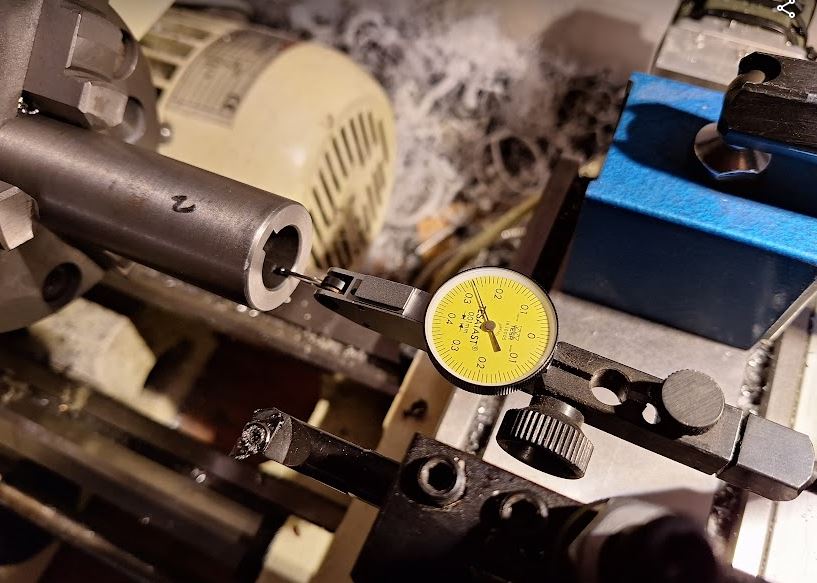
On the lathe, I used great care to center the sleeves precisely, to avoid excentricity.

Turning it to a larger hole diameter was easy, and a great surface finish.

Before fitting the motors to the machine, I did a quick desk test, and all working fine, out of the box!

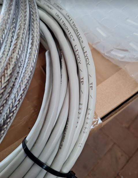
For the cabling from the machine to the control system, I selected LiYCY-TP (twisted pair) cables, 2x2x0.5 mm2, for the encoders, and Lapp Ölflex Classic 110 CY (shielded) 4Gx1.5 mm2 control cable for the power drive. These are a recommended and cost-effective solution for all kinds of servo and stepper cabling.

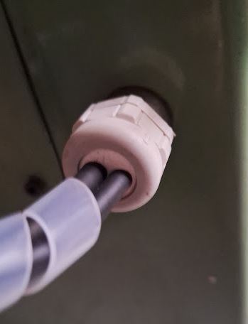
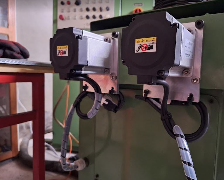
The motors were easy to mount, and the cables installed in the machine – a little oily and dirty task, but also a good opportunity to give the Z axis guides a good clean. Luckily, I had in stock 2-cable feedthrough plugs from a project about 30 years (!) past, from my childhood days! Now finally I can use these for the grinder….

The adapter plates were quickly milled on my CNC machine, all with great care for perfect centering. For efficiency, I used AlMgMn alloy 5183, which is easy to machine to high precision and practically free of warping or internal stress.

Installation went smoothly – a little tight fit of the motor flange, but hopefully, this will be a one-time installation.

The motors are rated to 5 Amps and more, but as expected, the typical currents are just around 1-2 Amps when moving, and 0.3~1 Amp when stationary.

Next will be modification of the X and A drives.

Tool Grinding Machine Saacke UW II: adding a high speed spindle

With the grinding jobs at hand, we often need to achieve very close tolerance of internal dimensions, say, resonant cavities or some rings, spacers, etc. that require internal grinding.
By looking to various classifieds, I found someone offering a large set of internal grinding arbors, accessories and internal grinding media for just a bit over 100 EUR, a steal.

The set of tooling and parts used to belong to an internal grinder, likely, a Kellenberger brand, with a HJN-828 Fischer spindle, operated in the southern part of Germany.

Many high quality grinding media, 16 mm, 20 mm and larger diameter, all in quite suitable grain size 46~60.

These are simply mounted to the arbors by epoxy glue. So you can re-use the arbor many times. With my light use, the grinding media will last a long time, unless I need to do some dressing for geometry, taking off a large amount of grit.

The adapters HJND size were all a bit rusted, but they are made from case-hardened steel, so they don’t loose precision too quickly.

Gave them all a nice polish, and some light stoning.

These are normally expensive, and I would like to use them, but the Saacke UW II has a Blombach spindle with a 1:6 ratio taper nose, there is no adapter from such cone to match HJND size internal grinding holders, unless you custom-make it – considerable effort managing balance and precision to micron levels. May consider it later.

Another problem is the necessary cutting speed, normally 20-40 m/s at the perimeter of the grinding body, which is beyond the capability of the Saacke (6000 RPM).

The HJN-828 is certainly a great spindle, 9 kg of mass! But the price… 20 kEUR, well, that’s above the budget!

Looking around, there are many options, like, used spindles, spindle motors, water cooled spindles, air cooled spindles. After all, settled for this VEVOR brand 1.5 kW air-cooled spindle, 3.5 kg mass, ER11 collet (can fit up to 8 mm shank), and 24000 RPM at 400 Hz. I will be running it in the 12000-24000 range surely, so there is less concern with the air cooling, which does require high RPM to function – if you want to run high frequency spindles at low RPM, better get a water cooled version!

It is specified to 2 µm runout – in fact, I could barely measure any runout, maybe 1 µm, on my surface plate. It is at the limit of what can be reliably clamped in a ER11 collet, and what can be reliably measured. Fair enough.

For the internal grinding, we need to use grinding media of small diameter, say, 20 mm diameter for a 30 mm inner bore – this requires rather high RPM.

The spindle comes with a VFD (variable frequency drive), at 400 Hz, the spindle runs at 24000 RPM, and I have added some configuration about the start and stop ramps to operate the spindle gently. An analog output is used to drive a display of the current RPM (voltage output 0-5 V scaled to show RPM as volts).

For the speed selection, start-stop, display, I repurposed some of the existing controls (and added some new labels and cables internally). All quite easy to do. Documentation is a little sloppy, because it will be a little different for each VFD, and easy to figure out. Power is taken from the contactor for the axis drives, so if the axes encounter an error, the spindle will power down.

The spindle is a 65 mm diameter, so I decided to mount it underneath the primary spindle, using existing M8/10 mm T-slots of the Saacke UW II.

After all that, some test run, without any holder – the Vevor spindle is working great and quietly.

The Vevor spindle’s primary purpose is engraving, wood cutting, etc., but not sure how long it will last if grinding dust will get into the bearings. So, we better protect the bearings. Sliding seals are no good option at these high RPM. So I decided to use an air seal, pushing compressed air through a narrow gap, at very high linear velocities.

Contemplating about the material, aluminum alloy EN AW-2007 was in stock here in suitable diameters, and in case of some incorrect adjustment, clogging, etc., it will be soft enough to avoid damage to the spindle nose (made of steel).

Inside, a groove at the perimeter to take a silicon O-ring, and air supplied from the side, with a screw-adjustable air flow regulator.

The air is supplied by a 6 mm PU pneumatic tube.

All mounted such that it doesn’t get into the way of grinding.

Now, we can do some test. The high frequency spindle fits well to the Saacke, the T-slots are integral to the grinding head and solid, there is no vibration or anything.

Surely, we won’t use that for very fast cutting, high efficiency grinding, or anything like that. These are all good items for productivity increase of industrial grinding processes, but here in my workshop it is enough to cut a few micron at the time, minimal load to the bearing and machine.

For some first test, ground a 45° chamfer on a steel part, just roughly machined, mounted in the A axis, and then ground the chamfer in steps of 0.02 mm, easy!

Another addition – an air blasting gun, optionally can also add cutting oil or water – minimal amount lubrication is not quite effective for grinding, but may help. For the time being, I just use it to blow away the dust, and then use a vacuum dust collector to avoid a too big mess – but eventually, just cutting a few 100 milligrams of metal, so it is not too large a mess anyway.

JET BD-920N Lathe: MESA Anything IO 7I92TF Upgrade

For more than 10 years (nearly 15) I have been using this small 9×20 lathe, marketed by Jet tool company, and it has served me well, certainly earned multiple times its cost. Years back I converted it to closed-loop (0.001/0.01 mm resolution glass-scales, spindle encoder) operation, so it can do the very precise and tiny work I do without any problems. Many people may consider this lathe inferior to the big brands and expensive machinery, but well, you need to buy a machine that fits your needs, rather than just something that is expensive and heavy and has little practical use. This lathe at least can run automatically, with CNC control, machining microwave resonant cavities, antennas, all kinds of fine-thread screws and stuff with no effort, once you have written good code to control it.
The motion controller so far is based on two parallel ports, running LinuxCNC software on an old Ubuntu PC. Ubuntu 8.04 released in 2008! Finally time for some upgrade. With more recent LinuxCNC versions, and new (used) PC, it is much preferred to let the time-critical tasks be done by external hardware, namely, the step generation for the stepper motors, and the encoder counting. Both of these tasks have been working to my satisfaction on the old parallel port based real-time system (30 µs base thread, 1 ms servo thread), but the encoder counting for 3 encoders was at the limit, and fast moves or vibration of the Z axis (long axis) sometimes cause skipped steps, leading to loss of dimension reference. Needs a faster counter to capture all of the glass scale encoder transitions – something that can’t be done over the parallel port.

After some research, I settled for a Mesa 7I92TF, because this card can easily substitute two parallel ports, without any need to review the circuit and cables, and will work much faster and independent of the PC running LinuxCNC – at least independent for 1 millisecond at a time. A long time for real-time Linux, and easy to achieve without much bother.

Received the Mesa card from a dealer in Portugal, sure the tax, customs and intermediate tradesman were ripping me off – a cards just costing USD 109, sold for nearly 200 EUR here… but at least, it works! Connection to the host PC is by Ethernet, using UDP protocol.

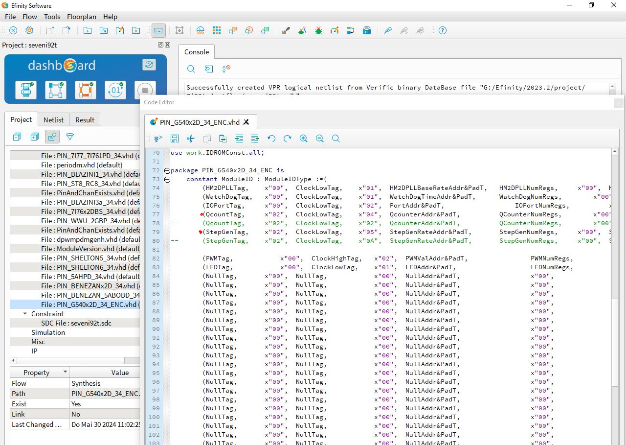
To modify the pinout to the existing cables, I had to alter the Mesa software, fortunately, the source code is available, and even the programming tools for the FPGA – the 7I92TF uses a China-made EFINIX FPGA, available free of charge.

By default, the 7I92TF only supports one encoder, but easily changed in the software, and because I have already signal conditioning circuitry installed, no need to by even more expensive add-on cards for the Mesa.

Here are the major changes, just used an existing, similar configuration, then changed the number of step generators (only need two) and encoders (need 3).

A quick bench test, and working very well – we have three encoder counts.

The software integration to the existing HAL (LinuxCNC configuration) was easily done – just change the parallel port pins to the Mesa pins, some other minor changes to load the Mesa driver, etc. – within less than 1 hour, all done.

The old stepper drivers and interface board still working fine. Just moved the parallel cables to the inside of the case – and connected the two DB25 headers to the Mesa card. For the pin header – luckily, had a ribbon cable to DB25 adapter in my collected, probably, since childhood days when I disassembled electronic scrap to scavenge some parts – finally that part is getting some 2nd use.

Final function test on the lathe – all working. Z axis moved in and out as quickly as I could, certainly would be losing counts on the parallel port encoder counter, but not here. The Mesa seems to count even the fastest moves without skipping a step.

Also assume that the system will have very good noise immunity – no more parallel cables and galvanic connection of the driver and PC, just an (isolated-by-default) Ethernet cable, that’s it!