Category Archives: Various

Measuring the Speed of Light: Fast light pulses, just about 10 m long

Revisiting some circuits built 15(!) years back – feels more like 10 years back, high speed light pulse transmitters and receivers. These come in handy to measure the speed of light. Nowadays, I would rather send out some train of pulses with applied digital modulation, say, a pseudorandom sequence, and then calculate the time difference digitally, from the received signal. This would surely be be very much more sensitive, but also much less instructive than receiving light pulses discretely.

The first motivation years back was a request from a school to build several sets of light transmitters and receivers, so that students could measure the speed of light by determining the time of travel of light pules. It follows closely this wonderful article of Mr. Ehret, unfortunately, I only have it in German:

Bernhard EHRET: Messung der Lichtgeschwindigkeit mit Lichtimpulsen.
Journal: Praxis der Naturwissenschaften. Physik, Volume 41 (1992) 4, pages 17-35

I built several versions of the light transmitter, the first sending pulses of small power, at a current pulse amplitude that doesn’t hurt the LED for a long time. Good enough for some shorter distance measurements. As a reflector, a back-reflector used for light gates is recommended (cat’s eye reflector), approx. 30×30 cm will do fine.

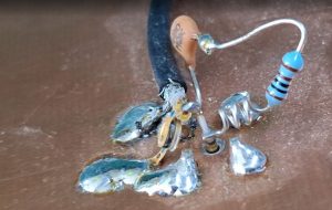
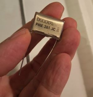
The schematics all are similar: there is an input capacitor, a current limiting resistor to charge a pulse capacitor, and a transistor used as avalanche device to generate the pulse. The pulse duration is very much limited by the LED rather than the transistor.

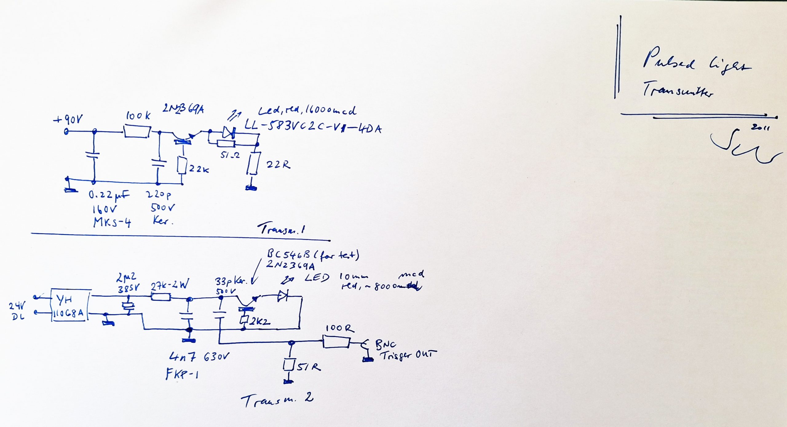
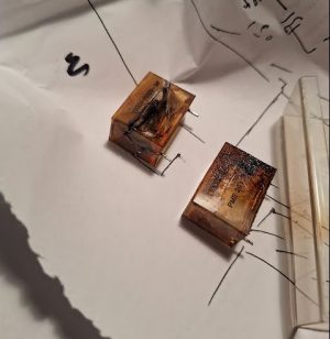
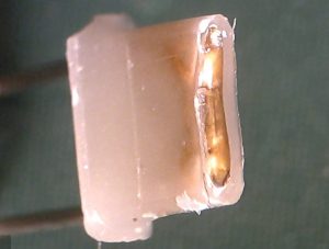
Mr. EHRET recommended a BC546 resistor, and I have also tried this first. The collector-emitter breakdown of the BC546B which I used in the circuit was above 200 Volts, and with the energy stored at such voltages in a 4n7 capacitor (a FKP1 Wima pulse rated capacitor), the LEDs used were quickly destroyed.

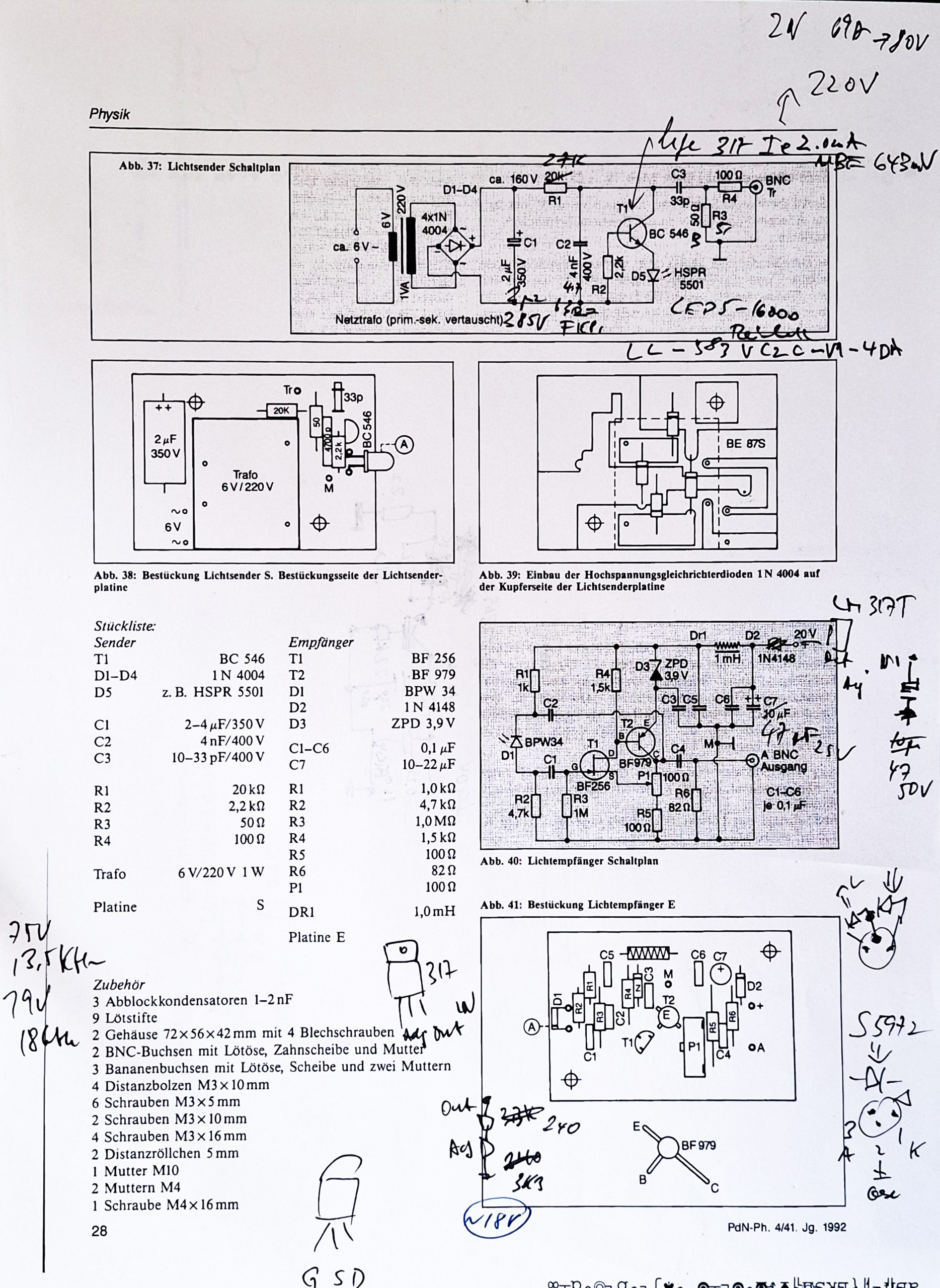
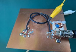
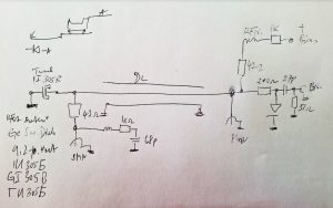
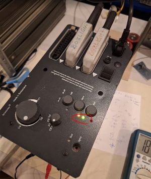
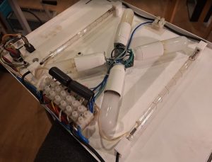
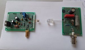
These are the two test circuits, the received and the sender, similar to the suggested circuits from the journal article, but with voltage stabilization of the receiver (LM317T added to regulated the voltage to 18 V).

The receiver is a wide-band FET-input amplifier, the resistors at the source of the FET are quite important: together with the PNP transistor, these provide negative feedback to counteract the Miller capacitance effect of the FET. The amplifier circuit could be replaced by any modern fast transimpedance amplifier, but hard to beat the cost of a BF256 FET and a BF979 transistor. Both parts can be replaced by similar devices, eventually with some minor adjustment of the resistor values to adjust the currents appropriately.
The photodiode, rather than the BPW34 I used a fast Hamamatsu S5972, because I had several in stock from other projects. The S5972 operates at low voltages, wide spectral response also for visible light and has about 500 MHz bandwidth.

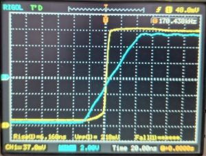
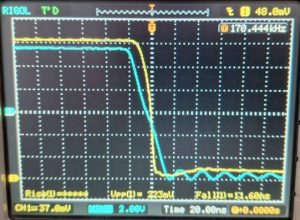
The transistor conductive breakdown will happen in less than 1 ns, but the pulse is about 43 ns long, because of the intrinsic properties of the LED, like, its inductance.

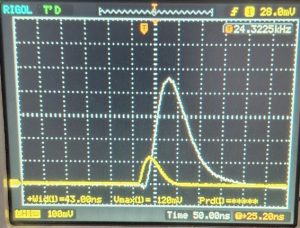
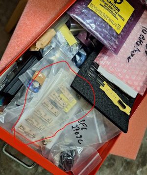
With the high breakdown voltage, it seems the light output is not much larger compared to the pulses generated by a 2N2369A at ~90 Volts, and there is considerably more ripple and noise at high breakdown voltages (white trance below is the BC546B circuit compared with the 2N2369A – yellow trace). Definitely, the classic 2N2369A (I have a stock of “JANTX” mil-spec tested devices and don’t recommend to use some copies or fake 2N2369 but rather metal TO-18 case old stock to be sure about the breakdown characteristics – modern versions and copies/fake 2N2369 may work well for common uses, but could have a completely different die inside, with random breakdown voltages).

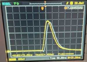
The 2N2369A gives reliable breakdown performance, and the rate of the pulses can be controlled by the voltage applied to the circuit, adjust to about 20 kHz, which requires roughly 90 Volts.

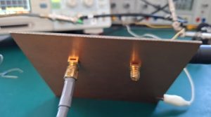
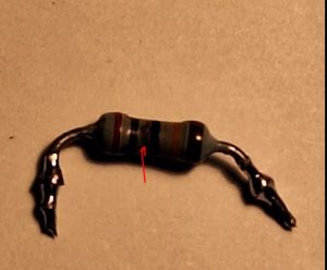
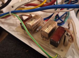
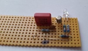
This is the board, with the BC546B soldered, it is a rather modern version of that transistor. Maybe I should have tried some older stock BC546B, BC238B and so on, but whatever you use, the breakdown voltage should not exceed 150 Volts, otherwise, you are at risk of damaging the LED. With high efficiency LEDs and 90 Volts breakdown, there is no practically relevant aging of this circuit, but at 4n7 capacity and >100 Volts, some aging will show up eventually. The lifetime of the LED will likely also depend on the pulse current, but the test circuit was build with rather low inductance traces (short wires, barely 1 cm), so the currently will be close to the highest obtainable. The LED could be soldered in with shorter leads.

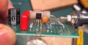
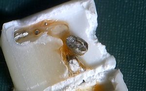
This is really the best choice, the 2n2369A!

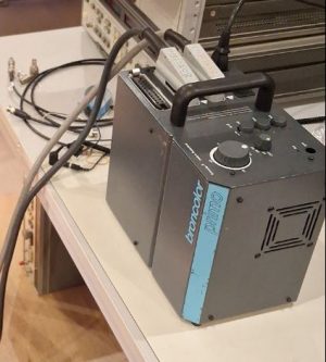
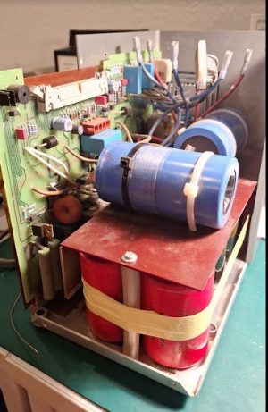
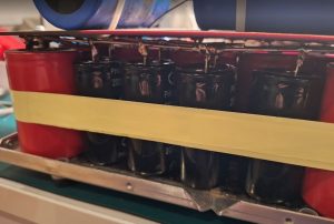
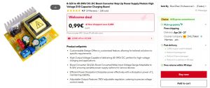
The high voltage the drive the transmitter is conveniently generated by a YH11068A DC-DC converter, available from Aliexpress for just a few dollars. Even though this module has considerable noise, it doesn’t disturb the receiver, and because of the current limiting resistor in the pulse, has also no effect on the pulse performance.

It is such a nice experiment and easy to build, some small danger with the DC voltage, but most of that circuit is severely current limited. If you have a scope that is capable of ~50 MHz bandwidth, it is a nice experiment for nights outdoors, and even kids will be interested to set up the mirror and see how light travels at limited speed.

At the time, I did also experiment with laser diodes, red and orange diodes ranging up to 35 mW, but there is no particular advantage in using these. Focusing a laser beam over 10-20 meters of travel it also not an easy task. Better just to use a LED, and large lens of appropriate focal length (say, 200-250 mm).

In the archives I also found some of the earlier measurements (note the datecode: September 2011), using a 54720a scope with a 54721a plug-in (4 GSa/s with 1.1 GHz bandwidth). Some pulses are barely 25 ns wide when measures correctly, which is less than 10 meters of light. I.e., the light pulse is so short that it is just about 10 meters “long”. The light source was a HL6323MG laser diode, a 639nm, 30mW AlGaInP laser diode of Ushio corporation.

Steep Edges: Revisiting some old tunnel diode circuits

A phone call recently reminded me about some experiments a long time back, using some tunnel diodes to generate fast edges. Various circuits were built at the time, this is one of the final working versions. All soldered to just a piece of double-sided circuit board with two SMA connectors fitted.

The trigger signal, a reasonably fast square signal is provided through the BNC connector. The bias circuit is separated from the tunnel diode by a few nanoseconds of delay line, which helps to make the transition stable.

From these “old days” I still keep many tunnel diodes that were at that time ubiquitous from the left-overs of even older soviet times (made in the late 1970). There must have been several boxes of tunnel diodes that made it to the Western market. Maybe from some surplus military sale or give-away, because many of the diodes are “military grade”.

The diodes are for various currents, like, 5 mA and 10 mA, and there are both GaAs and Ge (germanium) types. For this circuit, I have the 1i305B mounted, a 10 mA fast-switching optimized Ge tunnel diode.

With a bias of about 8 volts, roughly 8 mA of current, I get the circuit to trigger nicely. At the BNC input, there is a protection circuit (a DC block and a 1N4148 diode to limit the amplitude). Tunnel diodes are susceptible to soldering heat, so be careful and use pliers to conduct away the heat from the terminals while soldering. I solder them “from the side of the board”, melting the solder on the board or connecting part, and then barely dipping in the pre-soldered terminal of the tunnel diode for merely a fraction of second, then cooling it with my finger. Slight burns may result but the diode will be safe.

The rise and fall times are nice, the triggering is stable and precise. I have sold all my super-fast oscilloscopes (used to own a HP 54750a 20 GHz scope and a even a 54720a 1 GHz real-time scope, but sold these several years ago after completion of certain projects that required these – I don’t want to start a museum of test equipment so I regularly sell equipment that is no longer needed, especially equipment that is expensive and prone to degradation).

For the tunnel diode, there is even a datasheet available, albeit in Russian.

Easy enough to read with Google Translate, but even without translation, the key properties are obvious: peak and valley current, current ratio, capacitance. Over the years I have used some of these tunnel diodes to repair old oscilloscopes and trigger circuits. Typically, to substitute diodes that are no longer available (certain types of General Electrics) or otherwise prohibitively expensive. So far, never any trouble finding a suitable Russian diode.

A quick schematic from the archives, sorry it is not written very clearly, but already more than 10 years old. Left SMA is the output – there is a 47 Ohms series resistor, and a small network at the outlet to suppress ringing. The delay line is just a piece of regular RG 174 (50 Ohm) cable.

There are also datasheets for a variety of other tunnel diodes available in the Manuals’ archive, contact me in case you can’t find them.

Broncolor Primo: the photo flash is flashing again

A very unusual and dangerous repair, a defective photo flash. This is a professional unit, for use in photo studios. Generally, these units work by charging a big capacitor bank to 300-400 VDC, and then discharging this energy in an instant through flash bulbs. This unit has 10 pcs. of 2450 µF capacitors, charged to 360 VDC. About 1600 Joule, which makes this unit very dangerous, I would strongly discourage anyone not familiar with power electronics to even open the case.

For its size, it is quite heavy unit, and has a 16 Amp fuse, it will recharge quickly, drawing substantial power for a short time.

Inside are 12 large capacitors, 2 for the charging voltage stabilization, 10 for the capacitor bank. After duly checking the caps and their safe discharge state, I tested them all, each individually. 3 were bad: 1 completely disconnected at the terminals, 2 with no capacity, worn out.

Flash capacitor need to withstand high discharge current, so we cannot just use any ordinary cap but need to source “flash capacitor” – found reasonably priced one from China, because there were other faults with this unit besides the capacitors, there was no reason to by expensive caps first, without knowing if this unit can be fixed at all. Unfortunately, there are no schematics available.

Studying the electronics, there is a primary thyristor (TXN1012) switch DC stage, a type of coarsely regulated power supply. This had a blown transistor in its control circuit. Failed by arcing. Fortunately, I was able to still read the color rings under a microscope, and replaced the part and an associated Zener diode. Also the thyristor and a MOSFET in the thyristor were replaced (the MOSFET tested good, but I didn’t want to take a risk).

The replacement caps have 2000 µF. 3x 2450=7350, 4x 2000=8000, so I decided to install 4 of the 2000 µF capacitors (2450 µF were not available easily). It results in about 5% higher energy in one bank, good enough.

After some hours of complicated failure search and repair, some very careful tests (checking if the caps load symmetrically, which they did), finally the green light of the “flash read” LED was lighting up.

The flash worked – but only for a short time, then: SMOKE from the flash box. Expecting the worst, opened it up right away. Surely, first removing the cables from the capacitor bank.

Inside of the flash box, 4 Xenon? flash bulbs, with spiral trigger electrodes. The high voltage trigger transformers are right inside the flash box. The smell is awkwardly familiar: an exploded Rifa safety capacitor. 0.1 µF, 1000 VDC.

Fortunately, it failed open, as it is supposed to, lots of bad smell but no damage or fire. There is one capacitor for each bulb, a total of 4 (2 sets).

I cleaned up the mess, ordered 4 original Rifa (now KEMET, but they still print “Rifa” on these), and soldered it all back together. The other 3 were electrically still good (tested for leak resistance several MOhm, and isolation test passed at 1000 VDC), but had many cracks so I replaced all capacitors.

Eventually, all is working again. There is a built-in studio light, quite fancy unit. Hope the repair will last for a while!

ANENG MH15 Isolation Resistance Meter: a remarkable deal

Typically, I don’t report about test equipment acquisition unless these are associated with repairs, but this time, I will make an exemption. I used to have an old isolation tester, but it has been playing up, and with the analog instrument, difficult to repair. So I checked about more recent instruments, mostly, to check electric installations and motors and similar, for isolation after repair. This requires a 1000 VDC test, because some isolation defects tend not to show up at low voltage.

After a quick search, I found an almost unbelievable offer, just about 25 EUR! Shipping included!

One week later, a badly packaged box arrived, in a plastic bag, but without major damage.

Inside, a handy soft case.

The instrument, the plastic is of good quality. The red plastic is a little hard so it will not absorb too much shock when you drop the device.

Immediately, I got some of the highest value resistors I have in stock, a Remix 1000 MOhm +-5 % resistor. This is good to 10 kV, so there is no problem or leakage when doing a 1000 V test (other resistors may be have voltage rating of 300 V or 500V).

At a first glace, very nice result. -2% within the tolerance of the part.

Checking the voltages, 1000 V is fairly accurate.

500 Volts, even better.

Some more deviation at 250 and 100 Volts.

The specifications are quite good. But eventually, the instrument is not used much to measure resistance, but to check for conduction when 1000 Volts are applied. Normally, it will either show >2000 MOhm, or a spark will fly and the high-voltage isolation test has failed.

For completeness, also checked a 200 Ohm, 0.1% resistor. 1.5% deviation is the specification of the MH15, and deviation found is 0.25%, very good.

All in all, a great instrument for the occasional user, and one more reason to not skip isolation resistance tests.

L33 Thermal fuse: inner workings

Recently, I had a project that required a reliable thermal fuse. There was little space to accommodate the classical axial versions, so I did some investigations and settled for the L33 type fuses. These come in various temperature versions, here, the 130°C limit, rated 2 Amps, 250 Volts.

The main components are the 2 wires, a plastic case, and some resin. Having never studied one open, I disassembled a few good ones.

Clearly, the resin is filled to certain level. At the top, there is a bridge between the wires, made by low-temperature melting alloy (having tin, bismuth, indium and related metals).

The alloy is quite substantial, likely to be able to handle 2 Amps of current.

Triggering it with heat gun, the alloy melts, and there is enough space in plastic case that it forms a drop, effectively interrupting the circuit.

While the devices studied showed very good consistency of construction, a little overfilling with resin may result in the thermal fuse not opening, I hope the manufacturer has this parameter under strict control. For the 10 pieces I have, the weights measured on a precision balance where quite uniform at least. But if you get such critical parts from some doubtful sources, better you do some tests first and be sure they are reliable.

Blaupunkt OSTIA Home Radio: revamping an old beauty

As a family heritage, we ever had an old radio from my great-uncle (brother of my grandfather) named Modestus, and ever since I can remember is had been standing in the bedroom of my parents. Eventually, it was no longer used there and moved into my mechanical workshop where it still serves to play background music while I am operating machines.

It was build some time in the early 70s, and is based on germanium transistors – to be precise, 11 germanium transistors. The sound is not bad given the relatively simple circuit. However, in the last year it must have suffered some degradation of the FM tuner, because this tends to drift, and the reception is not clear always. Especially in winter, switching it on after a “cold” start, it needs some re-tuning after about 30 minutes of operation. A little inconvenient. Rather than spending a long time trying to fix an old FM tuner, I decided to take another approach – adding a new digital (PLL) tuner.

In my stock of old parts I had a no longer used PCI TV card, which incorporates a Philips FM1216MK tuner, a combination TV and FM tuner use a TSA5523 PLL, and can operate from a single +5 V supply (because of an internal DC-DC converter).

The card is a combined ISDN-TV-FM card. The tuner can be easily desoldered. Control is by i2c bus, two wire interface. Some libraries exist, but I didn’t use those. Rather straightforward to send the bytes needed to set the frequency and to do some more configuration needed. The tuner has a stereo decoder, but I operate in mono mode – there is only one speaker in the OSTIA radio.

A quick setup with a i2c LCD added for debugging. Using a Arduino Nano3 board clone with an ATMega168p microcontroller. But any microcontroller will do.

Now, integrating the new tuner to the OSTIA – my objective was to not destroy the old beauty, integrate minimally invasive. A first attempt to use the build-in transformer failed, because it could not provide the roughly 200 mA current needed for the Philips tuner.

To feed the audio signal, I cut a bridge on the board (which carries the FM audio from the old tuner), and injected the audio from the new tuner via a 100 nF foil capacitor.
For control of frequency, there is no an incremental encoder on the back of the radio (I rarely change the station if at all), and when you push on that encoder, the last frequency set is stored in EEPROM. The LCD has been disconnected, not needed during operation.

Finally, the OSTIA back at its accustomed place in the workshop. Reception is good and stable now, all frequency locked to a small quartz crystal.

Certainly this radio now has no longer just 11 transistors – maybe 500 transistors now!

NE555 Watchdog Timer: the ESP32 needs some oversight

The readily available ESP32-DevKitC boards have served me well in many application, but there are some issues with one of the circuits that is up all throughout the year in my house to record moisture and temperature levels. Occasionally, like, every few month, this ESP32 gets stuck, so the web server running on that ESP32 is not responding anymore, and the logging of the data will stop (red marked portions in the plot).

The root cause of that relates to the current pulses drawn by the WLAN circuits of the ESP32, and despite connecting a good USB power supply, proper cables, and capacitors, it seems that there are occasional issues that I haven’t been able to solve be capacitors, better power supply, or software restart-features. I added the later, but the ESP32 freezes to a level that any software reset triggered by the code won’t work. Shortly disabling the power converter on the ESP32-DevKitC (of the on-board 3.3 V regulator – its EN/enable pin is pulled high by a resistor) will restore the function and get the circuit started again.

As I am not always around watching this circuit, I added a good old trusted NE555 timer, which will send a reset pulse (by pulling the EN signal low through a Schottky diode), and the capacitor is shorted by the small MOSFET, as long as the ESP32 is sending a pulse (this is send every 10 seconds approximately, for a few milliseconds) — if the ESP32 gets stuck, there won’t be any pulses, and the NE555 will then reboot the ESP32 every other minute by cycling the power to the ESP32.

Hewlett Packard HP-85B: a marvelous desktop computer revived

At its time, the HP-80 series of computers were really desirable and expensive computers, mainly intended for control of test equipment and associated calculations. There is a screen, a printer, a tape storage device, all in one case.

For its age, still looking great!

Some cleaning of the CRT, and some other parts of the electronics to remove dust. But no other repairs were needed to the electronics.

All the shielding, all the parts, it seems to have been hand-assembled in small series, with each part individually checked and hand-labeled…

Only trouble is with some stuck keys. These can be operated, but don’t spring back easily.

Unfortunately, a common problem that can’t be fixed easily. Reason is the age, fatigue of the plastic. So I just switched the few broken keys with less-used characters. This is easily done by pulling on the white actuators firmly.

Surely, the HP-85B had quite severally limited memory, and there were many programs available that would need to be purchased piecewise, but thanks to great enthusiasts (google: EBTKS), there is a solution: the EBTKS extension board will provide huge additional memory, mass storage, and a replacement of the tape drive.

A little test program, to set the time, date (no year 2000 problem…), and even the printer still works (just needed a little cleaning).

The paper is thermal paper, but easy to read and can be even used to print simple matrix graphics.

LVDT converter: a Mahr P2004M, some electronics, and sub-micron resolution

Recently, I got a Mahr P2004M linear variable differential transformer (in short: LVDT), which is a device that can measure distance of roughly 2 mm with basically unlimited resolution. As the name says, it is a transformer, and the primary is to be fed with 19.4 kHz (or there abouts) sine, at 5 Vrms, and if the plunger is half-way in, the secondary coils with balance out, and there will be zero voltage. For any displacement from that position, there will be an appreciable voltage at the output. With the right amplifiers and converters, we can use this to measure distances extremely precisely.

To do some test, I mounted the LVDT in a height gauge, because I didn’t know if it was actually working.

The plug was broken, mechanically, but the little board inside was OK. So I replaced the plug, it is rather common 5-pin DIN plug with screw shield, same as is used for precision 100 Ohm Pt100 temperature sensors.

The circuit appears to have some capacitor, resistor, and an overvoltage protection device. I drew the circuit, but nothing special found.

For a basic test, I used a HP 3325B generator and a dual-channel scope.

Clearly seen, the LVDT is working. There is a certain phase shift of the incoming and outgoing signal, which is normal.

The noise is very small, well below 1 mV with some averaging. Note that the signal will probably go through a filter with 1 Hz or slower time constant.

To check the frequency response, I connected the LVDT to a HP 3585A analyzer, and clearly there is a peak sensitivity around 20 kHz. Better to operate close to that frequency (Mahr may specify 19.4 kHz for most of their sensors).

The Mahr datasheet also specifies how the input is supposed to be connected. There is a similar R-C circuit in the plug, at the other end.

Following earlier circuit designs, and also some Application Notes (Analog Devices AN-301 in particular), a circuit has been put together, consisting of a phase-shift oscillator with buffer and stabilized amplitude (TL431 used as a reference).

The key part is the switched rectifier, which is in a fixed (adjustable) phase relationship to the exiting signal. For adjustment, first null the comparator, then adjust the phase shift for precise switching around the zero point and check that this also coincides with the maximum amplitude at reasonable deviation from the zero position (about 1 mm of travel may be good for a 2 mm probe). The adjustment of the phase is fairly non-critical, but will ensure linearity around zero.

For some basic measurement, connected a 16×2 LCD, but finally decided for a 128×64 dot matrix display with white backlight. With that I can use large lettering which is easy to read in the workshop from a distance.

The full schematic, it a bit crude, may need to be re-drawn eventually. There is a power supply, +-15 Volts firstly, for the amplifier circuit, +5 V for the LCD and microcontroller, an ATMEGA128A.

The A/D conversion is done by an ADS1211U (even if the schematic may show ADS1210), a very reliable and highly precise part. A 24-bit sigma-delta converter. These parts don’t come cheap recently, about EUR 30 a piece, but fortunately, I had one in stock.
It has two separate power supplies of 5 V, one for digital, one for analog (with additional filtering): both are derived from the +15 V rail.

The switched rectifier for phase demodulation is done by a DG202 analog switch (all switches paralleled up for low resistance) rather than a FET transistor – simply because this is a way I normally design the lock-in amplifiers and phase detectors.

With everything arranged and tested, I put the circuit in a sturdy aluminum case. The switches are toggle switches that are easy to operate in the workshop. Sure we could attached various touch screens and buttons, but these are not convenient in a workshop with oil and dust.

The little device runs from 230 VAC mains, and doesn’t need much power at all (to most is consumed by the LCD backlight, which is LED based and supplied from the unregulated negative voltage via a resistor current limiter.

Finally, placed the LVDT setup on the granite surface plate.

So far working very well. There is no visible drift, at a 0.1 micron resolution. I have no intention to go below 0.1 micron in my workshop, as this is a metal working facility, no intention to fabricate telescope mirrors or optical parts.

Automated Basement Ventilation: keeping it dry

Basements in older German houses are usually pretty humid and cold, and there are various rules about the proper ventilation. You are supposed to open the window in the early morning, let some dry air in, but during the day, especially in summer, it must be closed. Summer air contains a lot of moisture, because the quantity of water that air can absorb strongly depends on the temperature, the so-called saturation vapor pressure of water. When such moist warm air enters the basement, it will cool down and water will precipitate on the walls. Not good. For me, this is all a bit inconvenient because rather than potatoes I store a lot of electronic parts in the basement, and I want to keep all as dry as possible. So I decided some month ago to set up a little system: (1) a window fan, (2) two humidity/temperature sensors, (3) an ESP32 to control the fan. As sensors, I use the ubiquitous AM2302, because it is easy to read and accurate enough.

For the fan, a KVVR K011301 Model, about 200 m3/h, it also has a feature to close the opening when the fan is off, so that no air can enter the basement when the fan is not running. In principle, you can also use two fans, one to supply air to the basement, and one to extract it, but for me, it works just fine with one fan to extract the air.

A little contraption made to fit the fan to the window. It is all reversible, so if I don’t like to use the fan any more, I can just fit the old window again.

A little control box was quickly made, with an ESP32 module, and a small transformer, a 5 V voltage regulator (be aware that the ESP32 needs pretty high peak current, several hundred mA in WiFi mode! So I needed to add some rather beefy capacitors. Next time I should use a larger transformer…

The key part is the calculation of the absolute moisture level. This is done by regularly (like, every minute) measuring the temperature and relative moisture level inside the basement, and outside, at a protected spot. Then calculate the saturation vapor pressure (which is a formula you can find in textbooks), and multiply with the relative moisture (in percent). This will give you a value that corresponds to the absolute water content (scaling to grams per m3, or similar, but I just use the hPa value, water partial pressure in air). If the water content outside is lower than inside, in absolute terms, I have the controller switch on the fan. There is some hysteresis to avoid all too frequent switching.

A nice box contains all the circuitry, and it can be accessed via a web interface, pretty handy. I also have a server poll the values every few minutes, to prepare some nice diagrams and to check if the system works as designed.

Indeed, it works brilliantly for several months, but then the AM2302 suddenly failed. It would read back the correct temperature, but the moisture value was stuck at 99%. Not good. I tried to clean the sensor, but to no avail. Also, this is the inner sensor, not exposed to the elements or anything. A is outside, B is inside.

So for the time being, I replaced it with a new AM2302, and hope it is just a freak defect and not a general limitation of these sensors — if it is, I will replace the AMS2302 by Bosch BME180 sensor.

This diagram shows the absolute humidity delta, outside minus inside, so if the outside is dryer than inside (for example, outside 10 hPa water, inside 12 hPa, the value will be negative, and the fan will switch on accordingly.

For now, in June, it is all working well, and the basement is indeed much drier than last year, and I don’t need to worry at all about closing and opening windows.

In this region, it seems that at least every few days there is reasonably dry weather for several hours, and the system uses these hours well to ventilate the basement thoroughly. Sure if you have rainy season in your country, this control won’t help, but it all the more moderate climates it seems to be a nice gadget to have.