Tag Archives: esp32

Tool Grinding Machine Saacke UW II: many new copper nerves, and a new silicon brain

With the basic installation of the servo motors complete, still some work to connect all the motors and encoders solidly to the controllers inside the (massive) control cabinet. First, wiring the cables through the base of tool grinder, a heavy iron casting. This casting is made of a rather hard type of cast iron, difficult to drill larger holes by hand tools. So I tried to to re-use existing plugs and connectors as much as possible. While for the power connections, there are plenty contacts of the big industrial connectors and cabling available, for the encoders I wanted to use twisted pair cable and plugs that are physically separated from the power cable feed-throughs and plugs.

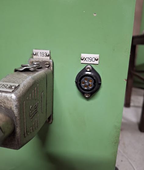
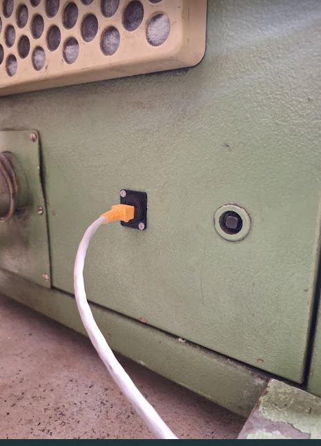
Shopping around, I found these Aliexpress plugs, from China, but with good IP rating, IP68. The cost is very moderate, and the size “SP20” happens to fit the openings and screws of the former fan power connectors.

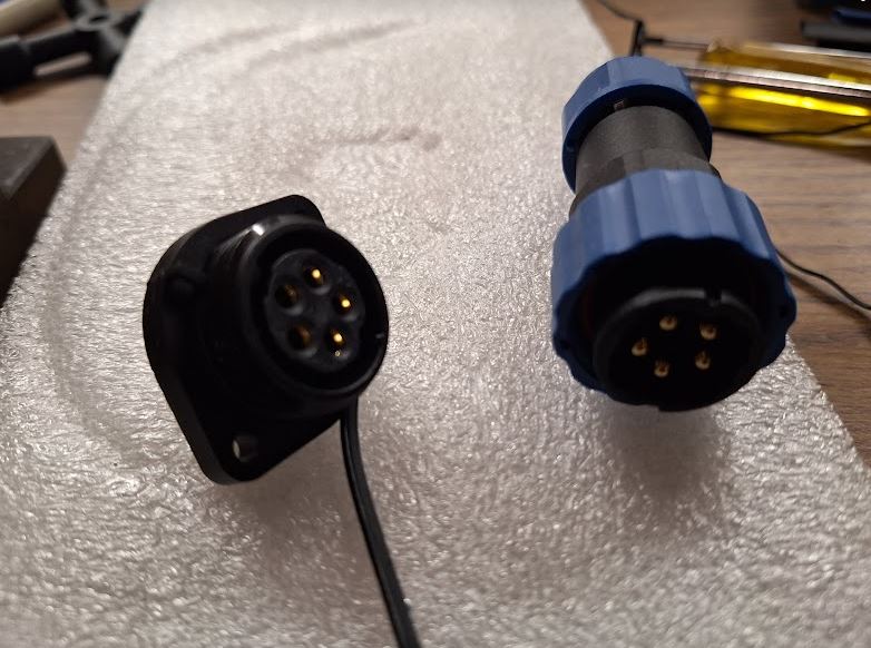
Fortunately, these connectors arrived quickly and there was no need for any modification of the machine base.

To guide the cables of the encoders (total of 4 cables, 2 twisted pairs each), there was not enough space in the existing duct. So rather than wasting time with pulling heavy cables, I just decided to add another duct from the machine base to the control cabinet, dedicated to the encoder cables.

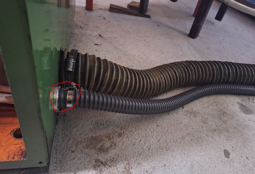
Installation was not easy – drilling a sizeable hole in the machine base took quite some effort, but eventually, the cast iron could not resist a sharp Cobalt-alloyed core drill.

Next, some important work inside the control cabinet. After removing all the old controls and motor drivers, there is now ample space available, but all we will need is a 160×100 mm board, and even that is mostly needed to connect all the cables.

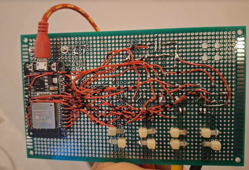
Key part is a ESP32 board, which does all the heavy work, on the other side, a W5500 ethernet interface, connected through SPI.

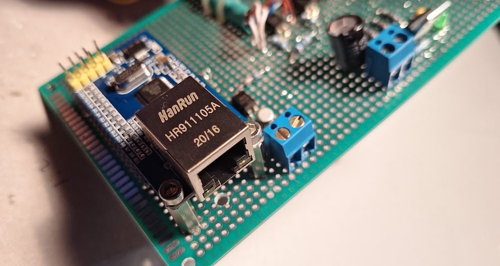
The soldering went faster than I thought, and the board is now mounted to the frame of the old control system. All powdered by a single 5 V power adapter (and an on-board 3.3 V regulator).

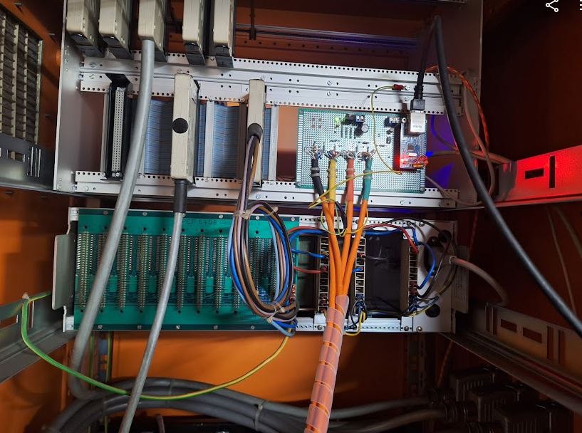
More time consuming that was all the other cabling, each of the controller has a 50 pin high density D-sub plug, with the fault, step and direction signals. I used some twisted pair (CAT) cable to make the short connections from the servo driver to the ESP controller.

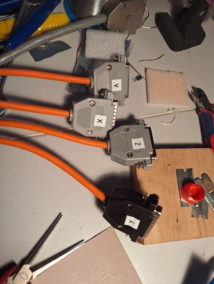
At the driver side, it now all looks neat, and also the connectors of the encoders were cabled with IEEE1394 (SM-6P) standard. Lots of work with tiny wires, heat shrink tubing, etc.

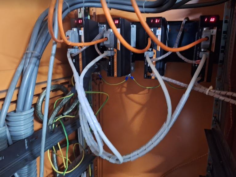
Finally, I mounted a CAT6 panelmount connector, so the whole grinding machine is now controlled by one ethernet cable, running UDP protocol.

Key part of this is the software, and while I have other machines running with (expensive and – in Europe – difficult to get) MESA cards, this time I resorted to a public domain development found on Githup. A really great project there. I managed to get some bugs removed and to make it work for my needs with 4 axis and one ESP32. The pin layout is quite critical, because the signals and the ethernet SPI will basically require almost all outputs of the ESP32.

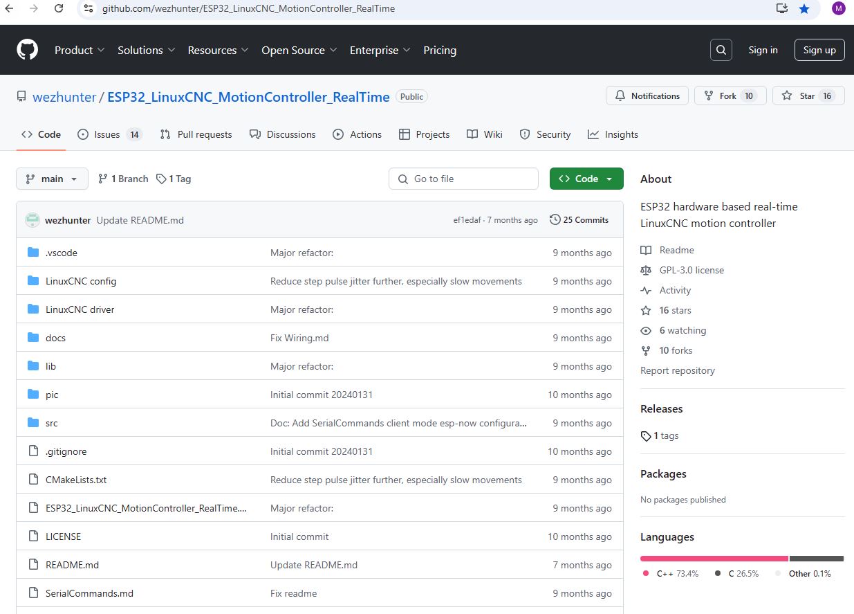
Some issue existed with the configuration, so I decided to hard-code the pins. Anyway, for now it is the only machine I have to control by this ESP32 motion control software, and there is no problem to customize it directly in the code.

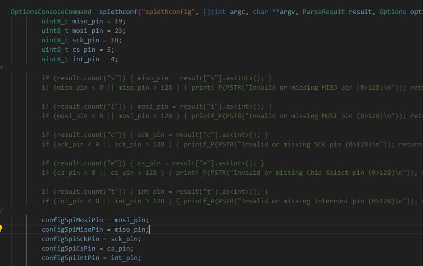
For those interested in detail, here is the port layout.

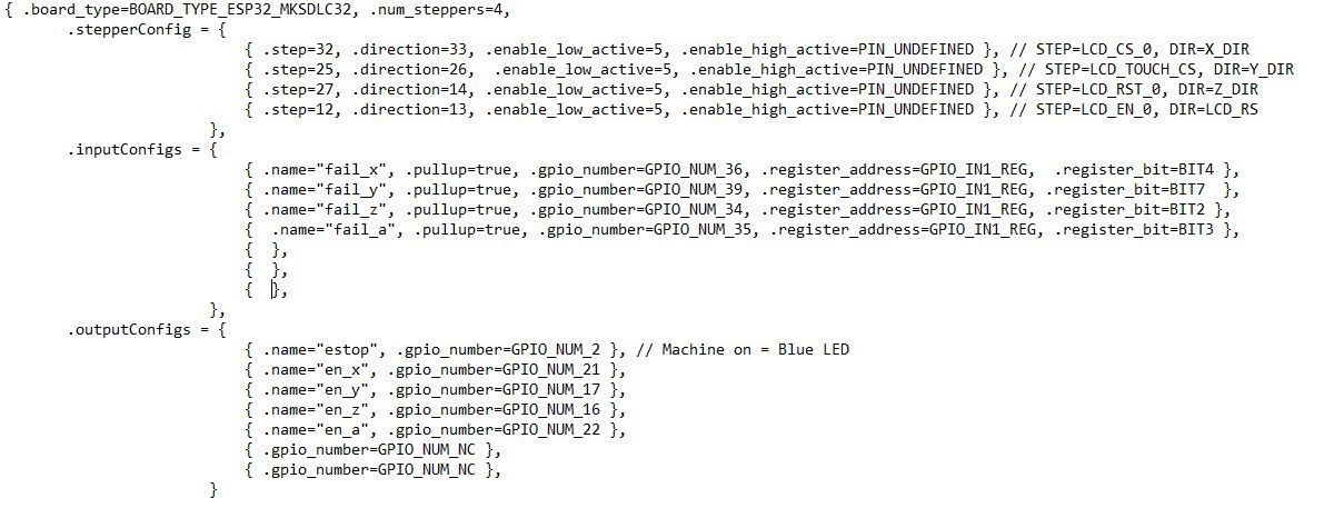
As before, the motion control will happen through LinuxCNC, with a HAL driver that is talking to the ESP32 through UPD updating the motion commands every few milliseconds. All the step generation and time-critical motion control tasks are done directly in the ESP32, so the communication between the LinuxCNC and the ESP32 is not that time critical. I won’t describe all the driver tuning and LinuxCNC configuration here in detail. Drop me a line if you are interested. Probably I can get you started on some own projects.

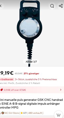
From Aliexpress, also another part arrived – a handwheel – rather low cost but good look and feel. This will be connected to a parallel port, because there is no time-critical events there, just reading the signals and linking them to a software quadrature encoder in the LinuxCNC HAL.

NE555 Watchdog Timer: the ESP32 needs some oversight

The readily available ESP32-DevKitC boards have served me well in many application, but there are some issues with one of the circuits that is up all throughout the year in my house to record moisture and temperature levels. Occasionally, like, every few month, this ESP32 gets stuck, so the web server running on that ESP32 is not responding anymore, and the logging of the data will stop (red marked portions in the plot).

The root cause of that relates to the current pulses drawn by the WLAN circuits of the ESP32, and despite connecting a good USB power supply, proper cables, and capacitors, it seems that there are occasional issues that I haven’t been able to solve be capacitors, better power supply, or software restart-features. I added the later, but the ESP32 freezes to a level that any software reset triggered by the code won’t work. Shortly disabling the power converter on the ESP32-DevKitC (of the on-board 3.3 V regulator – its EN/enable pin is pulled high by a resistor) will restore the function and get the circuit started again.

As I am not always around watching this circuit, I added a good old trusted NE555 timer, which will send a reset pulse (by pulling the EN signal low through a Schottky diode), and the capacitor is shorted by the small MOSFET, as long as the ESP32 is sending a pulse (this is send every 10 seconds approximately, for a few milliseconds) — if the ESP32 gets stuck, there won’t be any pulses, and the NE555 will then reboot the ESP32 every other minute by cycling the power to the ESP32.

Automated Basement Ventilation: keeping it dry

Basements in older German houses are usually pretty humid and cold, and there are various rules about the proper ventilation. You are supposed to open the window in the early morning, let some dry air in, but during the day, especially in summer, it must be closed. Summer air contains a lot of moisture, because the quantity of water that air can absorb strongly depends on the temperature, the so-called saturation vapor pressure of water. When such moist warm air enters the basement, it will cool down and water will precipitate on the walls. Not good. For me, this is all a bit inconvenient because rather than potatoes I store a lot of electronic parts in the basement, and I want to keep all as dry as possible. So I decided some month ago to set up a little system: (1) a window fan, (2) two humidity/temperature sensors, (3) an ESP32 to control the fan. As sensors, I use the ubiquitous AM2302, because it is easy to read and accurate enough.

For the fan, a KVVR K011301 Model, about 200 m3/h, it also has a feature to close the opening when the fan is off, so that no air can enter the basement when the fan is not running. In principle, you can also use two fans, one to supply air to the basement, and one to extract it, but for me, it works just fine with one fan to extract the air.

A little contraption made to fit the fan to the window. It is all reversible, so if I don’t like to use the fan any more, I can just fit the old window again.

A little control box was quickly made, with an ESP32 module, and a small transformer, a 5 V voltage regulator (be aware that the ESP32 needs pretty high peak current, several hundred mA in WiFi mode! So I needed to add some rather beefy capacitors. Next time I should use a larger transformer…

The key part is the calculation of the absolute moisture level. This is done by regularly (like, every minute) measuring the temperature and relative moisture level inside the basement, and outside, at a protected spot. Then calculate the saturation vapor pressure (which is a formula you can find in textbooks), and multiply with the relative moisture (in percent). This will give you a value that corresponds to the absolute water content (scaling to grams per m3, or similar, but I just use the hPa value, water partial pressure in air). If the water content outside is lower than inside, in absolute terms, I have the controller switch on the fan. There is some hysteresis to avoid all too frequent switching.

A nice box contains all the circuitry, and it can be accessed via a web interface, pretty handy. I also have a server poll the values every few minutes, to prepare some nice diagrams and to check if the system works as designed.

Indeed, it works brilliantly for several months, but then the AM2302 suddenly failed. It would read back the correct temperature, but the moisture value was stuck at 99%. Not good. I tried to clean the sensor, but to no avail. Also, this is the inner sensor, not exposed to the elements or anything. A is outside, B is inside.

So for the time being, I replaced it with a new AM2302, and hope it is just a freak defect and not a general limitation of these sensors — if it is, I will replace the AMS2302 by Bosch BME180 sensor.

This diagram shows the absolute humidity delta, outside minus inside, so if the outside is dryer than inside (for example, outside 10 hPa water, inside 12 hPa, the value will be negative, and the fan will switch on accordingly.

For now, in June, it is all working well, and the basement is indeed much drier than last year, and I don’t need to worry at all about closing and opening windows.

In this region, it seems that at least every few days there is reasonably dry weather for several hours, and the system uses these hours well to ventilate the basement thoroughly. Sure if you have rainy season in your country, this control won’t help, but it all the more moderate climates it seems to be a nice gadget to have.