Tag Archives: berger lahr

Tool Grinding Machine Saacke UW II NC: Fixing the Berger Lahr NI 3426 stepper control

According to my experience, failures of electronic devices have three main causes, 1, highly complex systems with inherent reliability issues because of all too many parts – these systems can only function with regular maintenance and repair, 2, high power circuits that run hot or otherwise stressful conditions, eventually, parts will fail, 3, bad design or insufficient design margin to reach lifetime expectations; even the best-designed system will eventually fail unless it is a very low power dissipation system of very low complexity (say, a telephone relais or a light switch).

Surely, for machine tools the life time expectations have been subject to change over the decade. 100 years back, a good metal working machine was made to last 100+ years, a major capital investment, and the complexity of such machines was kept low, heavy castings, and the machining done with conventional tools that had very little productivity overall – surely no comparison to the human-operated hand tools when it comes to machining metal, but also no comparison to nowadays high performance machinery. With the Saacke – a machine of quite some complexity with certainly over 1000 components, consisting of an estimated 30000+ single parts in total, 1000+ meters of wires, etc., the motors and controls have certainly held up to expectation after nearly 40 years, but the eventual failure of the NI 3426 can likely be traced to a combination of factors 2 and 3, say, the motor switching contactor selecting the Y-Z drive in combination with DC currents of 5 Amps, high inductance coils, difficult timing requirements of switching (only open or close the contactor after full decay of motor current), along with aging semiconductors and semiconductors of low design marking (e.g., C-E break-down voltage 125 V or the RCA 41013 used on the D190 current drive board, vs. 90 V operating voltage). It must have been some cost-performance evaluation at the time, along with the limitations of control systems for 4-axis control at the time, for Saacke to decide to select a single drive-two motors topology, and use one of the infeed controllers to drive either the Y or Z axis, rather than to provide drive systems and control for Y and Z individually.

A big advantage of the industrial electronics used here is their accessibility and serviceability, basically, all that would be needed are two new D190 assemblies, and you could bring back the machine to service within less than 20 minutes downtime, if you had certain Berger Lahr spare parts in stock. Barely a few hours if you had to pick them up at some Berger Lahr warehouse if you are in the South-West corner of Germany.

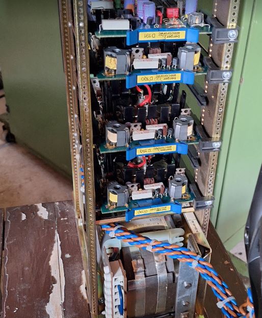
Their is ample free spaces in the case used to guide air through it with a big fan, keeping everything cool. The old engineers know that there is a direct correlation between operating temperature and lifetime of semiconductors!

There are the five identical current regulator cards, D190.

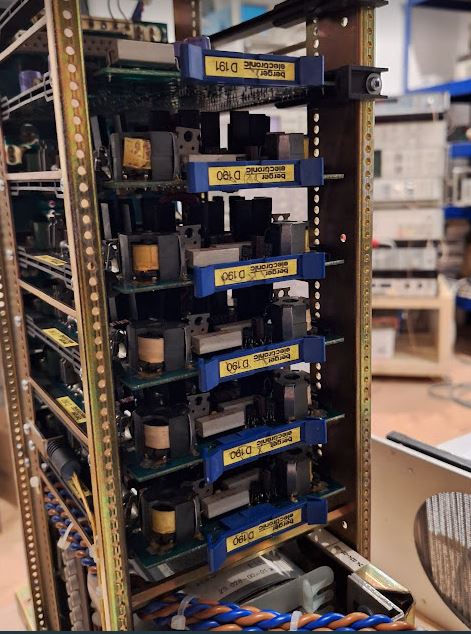
The “test points” for the current at the back panel – all the supply voltages, motor connections, and digital controls are routed through that panel, easily accessible for test.

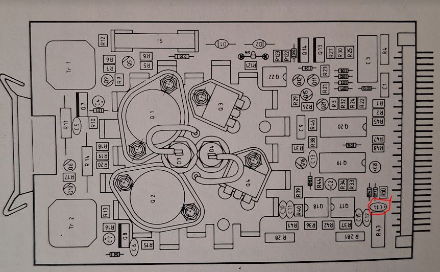
Surely, Berger Lahr has long been renamed and sold to Schneider Electric, and they even don’t respond to enquires of private individuals, nor offer any service documentation for legacy equipment, as much as I can say, is a supercilious company now that has no time to devote to service of legacy products. Anyway, we are an electronics repair shop here, and fortunately, some paper documents came with the Saacke machine, including, a schematic of the D190 board – without part numbers, but at least, identifying the location of parts on the board, and a detail functional description of the circuit.

Q12, BC237B, a typical 80s NPN small signal transistor, Q16, BC251B, a small signal PNP failed, along with the power transistors, a Texas Instruments PT1132 and a RCA 41031. Also checked the Q14 transistor, PT1131, a rather rare transistor, but it seems to be just a typical fast NPN medium power transistor, nothing too special, and, it is working!

Doing some further research, also desoldered the good power transistors from the boards, and check the current gains:
PT1132, hfe: one has 30, one has 25 (anyway, these transistors are good, no need to replace)
PT1131, hfe: one has 46, one has 21
RCA 41031: one has 33, one 109(!) current gain.

Definitely, we need to use replacement that have reasonably high current gain, say, at least 20, sufficient breakdown voltage, say, more than 150 Volts, and roughly 10 Amps current carrying capacity.

The BUX41 is indeed a good choice for these, and, because these are used even by Berger Lahr on some of their newer boards, surely valid replacements. It is not quite clear why they used a combination of the RCA 41013 and PT1132 in the first place – could be because of gain, voltage ratings, or switching time considerations.

To get some BUX41 is rather easy, but prices are in the range of 5 to 15 EUR a piece, well above what I am willing to spend on a repair attempt, given that I need 8 pieces (no intention to re-use the working power transistors, because they may eventually fail or may have suffered some damage.

A kind reader of the earlier post pointed me to the “Tesla”-made devices, KUX41N, these would really be a good choice, but I would have to buy them from outside Germany, and there is no easy way to order them from Germany.

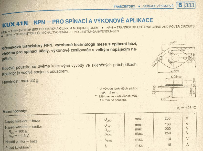
In some past project I have used power transistors of Tesla brand, and these really held up well, heavy duty cases, strong wires. They didn’t save on copper when making these.

The cheapest I could find were some BUX41 on Aliexpress. It says real but looks fake (the vendor even removed the “ST” logo on the picture”), anyway, let’s order a few.

After short waiting time, an envelope arrived with the “BUX41” transistors, and following good habbit, I had ordered 10 pieces, 8 for the repair job, 1 spare, and, one for fake analysis. These may or may not be original BUX41 dies, but it is good practice to have a look inside these to check at least the silicon area (sometimes there are just very tiny transistors inside that won’t be able to deliver the current), the heat conduction pad (sometimes absent), and the wire bonding (sometimes lousy). In my case, the BUX41 looked quite good inside.

Solid bonding wire, a strong heat conduction bag, solid case. Only the marking comes off easily, and the cases look polished/ground with sandpaper on the top.

So these must have been some generic high-power higher-voltage higher-gain NPN transistors that were then labeled BUX41.

When doing gain tests, 6 came out as 35-45, 3 as ~25, not bad. Used the higher gain transistors for the upper section of the H bridge, having the transformer driver.

Further testing the Aliexpress BUX41, I pulled out my old Harrison Laboratories 6209A 320 Volts D.C. Power Supply. With the base floating, not conduction up to the maximum voltage, roughly 325 V over the E-C junction. Also checked the RCA 41013 (good parts), and these break down at ~140 VDC.

With some fresh heat conduction paste, all the transistors mounted and soldered to the D190.

The small signal transistors, even found an original BC251B in my collection, but no BC237B – replaced it by a BC547B.

With the transistors installed, I checked all the transistors and diodes with a diode tester, to check the voltage drop, and compared it to a good assembly. Also checked all the voltages at the electrolytic caps, with the diode tester. Good practice to check for shorts.

Next, I connected the circuit to a power supply (+12 V, -8 V are needed) – the circuit is operating fine, the H bridge switching properly. Then I dared to install it back to the Berger Lahr drive, and powered it on.

One of the largest stepper motors ever on my workbench, it starts to turn. Repair success!

Also left it switched-on and turning for some hours, temperature is low. Regulated the current to ~3 Amps, plenty enough for that motor unless you need maximum torque.

Tool Grinding Machine Saacke UW II NC: getting the axis drives turning

Now with the tool grinder placed at its final location, time to have some more study of the electronics. Objective is, to get the drivers turning in the XYZA directions again, and then to determine the path forward. Surely overall intention is to replace the existing PEP control computer by a LinuxCNC-based motion control system, so I can control the machine with ordinary G code and use macros and such to easily do any kinds of grinding cycles without relying on computing technology of the 80s. Also, the affordable technology at the time has been limited to one axis or two axis simultaneous movement, but we are targeting 4 axis (at least 3 axis simultaneous movement. For the Saacke machine, the Y and Z axis were controlled by an independent, TTL logic based “infeed control”, with parameters set by a number of BCD switches at the front panel. Pretty useful for recurring tasks, but hard to program special features just by BCD switches, and, of course, each grinding cycle needs to be set again by hand – you can keep the settings in a notebook but there is no way to just load a program by clicking a button. If you make one mistake on the BCD switch, rotary switch, etc., the machine will likely crash in the old days…

First of all, we need to get power to the electronics, and there is some unreliable start-up condition to the circuits controlling the mains power to the axis drivers and control section. That power is switched through contacts of the K38 contactor, which is turned on if the voltage monitoring contactor K123 is actuated, and the K124 safety contactor is actuated. K124 state depends on the limit switches of the axis, if any of these normally-closed switches opens, power to the drives is immediately cut off, so even in case of some control system malfunction, the power will be interrupted safety. There are nice slide rails, except for the Y axis, where the limits can be set by an Allen key, so that you can limit, say, the X travel to within reasonably safe limits if there are any particular fixtures mounted on the table.

The K123 contactor is actuated if all current signals (closed contacts of the X and A axis drive controls, K400 and K401 relais) and the control voltage (nominal 24 V) is good, but it also has a feature that it will not re-actuate if tripped, by the 3-4 contact pair. So, if there is any fault with motor current or control voltage, even once, the machine will stay in that state until it is power-cycled by the operator (after correcting the error, hopefully).

However, at initial switch-on of the main switch, surely there won’t be any good control voltage, and with the trip function, K123 needs a current path to switch-on at initial power-up, which is done by the K10 time relais. This device closes a contact and actuates K123 for just one second, when powered on, then, opens and stays open until the next power cycle.

It is a little dated version of still available devices from Dold Mechatronics, AI983N.7100. The inner circuit is some simple monoflop circuit, some capacitor, a relais – and, a transformer.

Turns out, there is no voltage on the transformer secondary – the primary winding is open circuit. Heavy glued to the circuit board – these devices are made to be in a vibrating factory environment, but the circuit board is of pretty ordinary quality, not through-plated.

After a quick repair – fortunately had a similar print transformer in stock – and replacement of the electrolytic capacitor, K10 is working fine, and the drives are now powering-on normally each time the mains switch is set to “ON”.

With power now established firmly, to the axis motors. The Y and Z axis (Y is moving the spindle up and down, Z is moving the spindle forth and back – similar logic to a horizontal milling machine) is driven by two independent stepper motors.

These are pretty sizeable Berger Lahr RDM51117/50 frame size 110×110 (NEMA size 42) motors, pretty expensive back in their days, and some of the strongest stepper motor available in the market.

Current rating is about 5 Amp per coil, 500 steps full step, 1000 steps half step.

Because of the lack of computing power and also lack of immediate need, there are two motors, but only one drive! The drive used for infeed automatic control is selected by some switches, including rapid functions. The current is turned off during switch events, surely, never unplug or cut the current of a stepper motor while energized – it will likely damage the driver transistor.

The drives are “Quintronic” NI series drives, very solid built.

Made in Western Germany – probably all hand assembled, and with one dedicated logic control board, and 5 D190 current control boards (one per coil) – powered by a 90 Volts DC supply, rated at 750 VA.

However, before being able to tests these, need to get control signals (TTL level) from the LinuxCNC PC to the old control system (running on 24 V HV-TL, respectively, open collector inputs).

Copying some circuitry I found in the Saacke old interface, using 7406 and 7407 open collector, some resistors, and a high-voltage tolerant LM311 comparator, soldered together a small interface board providing two step and two direction signal conversion. These also connect to some counters for the A and X axis at the front panel that I may use later as an auxiliary display.

In order to select the Y or Z axis controls, I also re-wired some of the feed selector circuitry to two small Finder relais, driven by a small control board.

The control boards – no schematic even needed, just a TTL relais driver, so there is double isolation – the PC TTL level with its own ground and 5/24V rail driving a small relais, which in turn uses the 24 V control voltage of the Saacke machine to actuate the Finder relais. With such industrial controls, contactors, motors, chopper-based drives, etc., it is very critical to use low impedance noise-insensitive circuits, rather than just the thinnest unshielded wire, common power supplies, etc.

The Y and Z motors are switched to the driver by Siemens contactors K200 and K201, which need to carry the 5 Amps DC at a very low resistance, say, 0.1 Ohms, to not upset the current regulator. Coil resistance of the steppers is barely 0.5 Ohms. Generally, I would consider this a problematic setup, firstly, because the contactor resistance may not be held to these very low resistances over time, also, there is no precise timing of the current-off signal to the drives, and the switching (happens at the same time, but may be milliseconds or 10s of milliseconds misaligned). So, there may be some arcing in the contactors, etc., and eventually the contactors or the drives may fail. Upon closer examination, indeed, a different, newer Berger Lahr drive is in the cabinet, compared to the X and A drives. Likely, it had failed, and then been replaced by a unit from a different machine (still has a label corresponding to the “X” axis – the table traverse).

Next, the control circuit – the drives are controlled by common step and direction pulse signals, originating from a rather large card with some TTL logic on it.

For convenience, I added the new small control/level converter boards to one of the old control cards, with a temporary DB15 connector to cable it to the PC.

Next up, confirmation of the phase currents. The cables of the stepper motor DC supply are fortunately routed such that a simple clamp-on current meter can be used to probe the current of each motor phase without any need to disconnect cables.

The X driver had one phase at only 3 Amps of current, rather than 5 Amps, strange – the motor was still working normally. Fortunately, I have the manual and schematics (at least the schematics without values and part numbers of the circuit elements) of the D190 current regulator boards of Berger Lahr company, so it was easy to find the culprit. A tantalum cap, not shorted, but soldered with incorrect polarity. Very likely this problem existed since manufacture, and slipped through Berger Lahr’s quality control system. Maybe the tests for quality were done at a lower current, say 3 Amps, because the reversed tantalum acted like a voltage limiter at about 3.5 Volts.

Easy fix, replaced by a multilayer cap.

The current input is normally operated at 5 Volts, and a trimpot is used to adjust the phase current of each coil.

Unfortunately, the Y/Z driver has some problems, keeping unstable current regulation on two phases, and after a short time and trying to adjust it, blew the fuse on two of the phases.

The D190 current control cards apparently used several types of transistors, I tried to collect what I can about these, some are very rare PT1132 transistors, other expensive NTE386, some use BUX41 and PT1132 in mixed (PT1132 for the upper transistor of the H-bridges, BUX41 for the lower). Nowadays, we would design that with MOSFETs and some high side drivers, easy enough.

The PT1132 seem to be related to BD245 or similar, or BUxxx series transistors, like, BU426.

Surely, we need NPN transistors with reasonably high gain, to avoid overloading the high-side drive circuit, and rather high voltage resistance (because of the 90 VDC), and fast switching – because the transistors won’t be able to sustain the linear load region to the 0.5 Ohms coil resistance for any length of time.

Later, it seems, Berger Lahr used BUX41 a lot, 200 V, 15 Amp NPN.

Yet, another type of BUX41…

NTE386 devices, very solid devices, but expensive, more than 20 EUR a piece!!

Finally, I would like independent motors and controls for both Y and Z, to avoid complicated switching and programming, and surely no full-current switching between driver and motor – surely retire the K200 and K201 contactors.

The are some options,

(1) Repair the Berger Lahr D190 cards – will surely repair these after sourcing some BUX41, but this will need to wait for some winter days and less busy times. Even consider to modify the H bridge on the card, by using MOSFETs and modern drivers. The drivers I have have combinations of PT1132 with BUX41, and PT1132 with RCA 41013 (equivalent to BDY58, NPN 125 V – 10 Amp, current gain of at least 20).

(2) Replace the 5-phase steppers by some NEMA42 bipolar steppers, with conventional microstep drivers – easy to maintain and repair going forwards. Then I would have some spare control cards from the former YZ driver, should any cards of the X and A axis drivers fail.

(3) Consider using more modern drive topologies like AC servos with encoders for the Y and Z axis, even for all axis, one I have figured out necessary adaptions of drive geometry (shaft diameters, case diameters).

With all the troubles of the design and state of the Y and Z drives, the X and A axes are working very well, even with the dated drivers and motors. 1000 steps per revolution results in about 3 mikron per step, and the speed of the table can easily reach 500 mm/min and more (mostly limited by the maximum step speed of a LinuxCNC real time step generator over parallel port) – given that it has a ball screw and roller ways, the mechanics would certainly tolerate more without any problem. Also confirmed the very smooth action of the table, mechanically no problem at all with the machine. Also the Y and Z axis – mechanically – are very sound. Cleaned all the screws, guideways etc., from the black dust and grease (better not use grease on grinding machines, but some CLP or HLP 46 oil).