Category Archives: Various

LH0021CK Power Opamp: an analog autopsy

From an earlier test equipment repair, I had two broken LH0021CK power amplifiers, both died because of a design issue with an YIG driver board (lacking distance of a heat sink from a board trace leading to an occasional short circuit).

The LH0021CK are +-12V output, +-18V input, 1 Amp capable devices, and if treated nicely, they will last 40+ years of service. Still available today, despite being obsolete, at prices ranging from 10 to 300 EUR a piece. These were quite common parts in high-end controllable power supplies, servo drivers for scientific instruments, and similar apparatus.

Finally, I cracked these open – not anticipating the fragile ceramic substrate inside.

I pieces together a picture from multiple images, because this part is a little too large for my microscope, and too small for other cameras to see it clearly.

The datasheet provides an internal circuit diagram, but is there really a 741 opamp inside? What about all these resistors?

Checking the parts, indeed, there are 4 discrete transistors, laser-tuned resistors (you can see the burn lines of the laser to adjust the value of the resistor in processing of the circuit, some have even two tuning lines), and an opamp die.

Eventually, I opened two of the broken parts, an old one, golden case, and a newer one, silver case, both made by National Semiconductors. There are some small differences of these parts, also related to the circuit. The resistance values are rather similar, but the newer part (shown in the picture) has an additional resistor at the COMP input. Both parts have no connection of GND to the negative supply input of the opamp – this is apparently a mistake in the schematic shown in the datasheet, because the circuit wouldn’t work if there is such connection.
The newer part seems to have a small diode chip (marked light blue), but checking it just gave a 0 Ohms value. Maybe just spacer for wire bonding.

The failure mode is clear for both parts – the SC+ bond wire is blown (with molten ends clearly visible), and the Q4 power transistor shot.

Clearly this part could save a lot of space in the old days, replacing it with discrete parts would take about 5 times the space (1 large TO-3 NPN, 1 large TO-3 PNP, 2 transistors, one TO-99 Opamp, and several resistors…. I have been successfully replacing these parts with TDA2030A audio amplifiers, they seem to be be a good substitute, even if they may lack some detail performance characteristics (eventually, the TDA2030A has even higher power and better bandwidth, say, 100 kHz vs. 20 kHz).

Some detail study of the opamp die showed that it is indeed a National Semiconductor part, 741H printed on it, and the shape of the capacitor (the light colored silver area in the middle) is the shape of the typical National 741.

Sennheiser Momentum 4 Headphones: water and a corroded connector

Normally, I don’t repair consumer electronics, but in this case, a good friend asked me to have a look at these expensive Sennheiser headphones. Apparently, some water had entered the case, and since then, these were not operational. When charging, it blinks the red led 3 times, pause, 3 times, and so on. No other sign of activity and no success to reset it by pushing the button even for a long time.

To have a look inside, you have to first remove the ear protectors, then remove 4 screws, and gently pull-out the speaker. Exercise great care! There is a flat cable to connect the microphone to the intermediary board (the same board that has the battery connector). The flat cable and connector can be easily damaged, better use small tools and a microscope.

The battery connector had signs of visible corrosion. Probably cause by the combination of water and electric power. The battery has about 4 Volts when charged, so it can easily cause electrolysis of water and generate corrosive products if the water contains traces of salt, etc.

Unplugging and re-connecting it, using some contact cleaner, I was able to establish a stable (electrical) connection again.

The battery is contained in a small case, broke it a little when opening, all these internal parts are pretty fragile. But still functional. Inside, the cell is just attached by some double-sided sticky tape.

Here, a close-up of the microphone connector. It needs to be opened with a needle or tiny screwdriver by lifting the black part carefully. Easy to break!

For the current headphones, there battery was still good, but there are spare cells available. The quality of these may be variable so you may better check them before using as a replacement (e.g., by giving them 10 or 20 cycles by an external lithium ion charger). The price is quite OK, but you wouldn’t want to open up the speakers every few months for a battery replacement. The Sennheiser factory battery may last for about 3 years of use.

Agilent 4352B VCO/PLL Signal Analyzer: see you again, after 5 years

After some years, again on the bench, a trusty 4352B VCO/PLL Signal Analyzer. A rather specialized instrument, but hard to replace with any more recent instrument, unless you are shopping in the 50 kEUR+ category.

he earlier repair: Agilent 4352B VCO/PLL Signal Analyzer: working! – I left a mark inside the cover, as I typically do after performing significant repairs.

Over time, the display has aged and unfortunately became unreadable. Not a big issue, because there is a connector for an external monitor, but still not very practical to use.

The polarizer can be pulled off, but the glue stinks and is very sticky, would be a big effort to do a polarizer repair.

The LCD, a Sharp LQ9D340H is still available, but the cost is high, even when sourcing from China, about 200 EUR a piece. Note: don’t mix up the LQ9D340 with the LQ9D340H – these are not necessarily compatible according to the datasheets.

After some study, I found a good offer for a used LQ084V1DG21 8.4″ 640×480 Sharp LCD panel. These are compatible with the 340H.

Offer of a German IT used parts seller:

The used panel had a special adapter – not compatible with the Agilent flat ribbon adapter of the 4352B – removed the screw and the adapter with no problem at all.

The installation went without any trouble.

The new LQ084 is a little thicker than the 340H, but it all fits into the LCD compartment.

The backlight driver and even the backlight cable position are compatible – just needed to plug the new LCD in.

Finally, not too much to do further – close the case, insert the screws, a quick test run.

Flawlessly working – starting up like before – and, I didn’t even have to remove the inner cover or any boards – just the front panel and LCD compartment.

Heraeus K1150/3 Oven: some cosmetics, some bricks, some electronics

There is always some need for heat treatment in my workshop, for example, hardening, softening, tempering of steel, hardening of aluminum alloys, etc., often just done with a torch and by visual judgement and feeling more than measurement. While this works for small parts and general tool steel quite well, it doesn’t work for hardening of aluminum (precipitation hardening), and larger pieces of steel may crack. Even smaller pieces may suffer from uneven heating, resulting in distortion.

A small electric oven is handy for that so far, a German brand, “Naber”, already pretty dated but it seems to have been very rarely used. Not long ago, added a controller, to allow curves and automatic controlled heating and cooling operation.

But recently, screening to classifieds, I found a much better oven, 4-side heated, Heraeus K1150/3 that can handle much larger pieces for heat treatment.

It came pretty quickly, for just a little over 400 EUR, including delivery and including a cart. First thing I did, painted the cart a little with red paint – RAL3000 “feuerrot” as it is called officially. For years I carried around a can of such red paint, never thought I would ever actually need it.

The oven, it can operate of 3 phase power, 380 V 14.5 Amperes, originally. Now with a mains voltage of 400 V, the power will be about 10% more. In any case, I can connect it to my 16 A outlets.

The oven has quite significant heating power for its size, good for heating up metals quickly, for hardening. Also, it is built such that it can be opened pretty safety in hot conditions, to take out the glowing parts – not all ovens (especially not common pottery ovens) can be opened when hot – the refractory bricks may brake, or the coils may bend, or similar.

The next difficult task was to get the oven back onto the cart, not easy, because of its bulky size and well over 100 kgs of weight. Even with 3 people, impossibly to carry, and not easy to grab. But with various pieces of wood, some small furniture rollers, eventually managed to get it onto the cart with the help of a friend, and no damage or injury!

The bricks of the oven are all in good state, except for some loose parts at the front door. There, the inner (hot) layer is held to the door by 4 metal parts.

With refractory glue, stable to well up to 1100°C, and easy to use.

To do a proper job, I cleaned up all the old cement, and thoroughly roughened the mating surfaces.

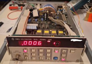
By the manufacturer, the oven has a very sturdy Pallaplat (Au-Pd-Pt vs. Pt-Rh) thermocouple, very thick wire, certainly worth almost the 400 EUR I paid for the whole oven, connected to an analog temperature regulator and a nice 96×96 mm instrument.

These Pallaplat thermocouples have a larger coefficient (several times larger) compared to common Type S (Pt-PtRh) thermocouples.

My intention was to keep the old regulator and instrument as a maximum temperature regulator basically, and add a (secondary) controller with ramp/segment control. The oven, fortunately, has already provisions for a second thermocouple, so I pulled two new isolation tubes and a new S-type compensation wire from the oven to the control cabinet.

Be careful when connecting compensation wires for thermocouples, because the color codes are misleading: BLACK is positive, RED is negative!

To make things even more complicated, there are colors codes that differ from country to country…

To install the new temperature controller, we need to modify the control cabinet a little. There is a timer so far, which will not be needed anymore, but the opening is not quite large enough.

Cutting a a little larger with a grinding disc, filling, quite laborious to do it precisely!

It is a nice part, with many functions and a complicated manual, but it works pretty well.

Rather than an expensive Western part, I resorted to a part imported from China, model PMA-900. It is available in various option, alarms, control output choices and so on.

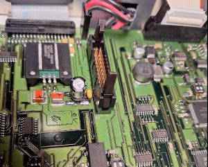
Heraeus used a Siemens contactor to switch the heater on and off, but for finer control, I selected a 40 Amp solid state relais, which can modulate the power much more precisely, and without wear.

Installed – the heat sink came with the relais, and there is a small fan to keep it cool even in the control cabinet. Later, I added a plastic cover for touch protection, and some warning signs. 400 Volts is no joke!

The S-type thermocouple, about 300 mm long, I also got from China, at a very reasonable price. It is already protected by a ceramic tube, but the diameter didn’t fit the existing hole, and it looked all too fragile to be easily damaged with rough handling and over time.

Fortunately, I found a surplus protection tube, exactly the right diameter (inner and outer), made of 99+% sintered aluminum oxide. Just, a little long.

With a diamond wheel I cut it slowly, because it is a single piece not easy to get again (new protection tubes of this kind nearly cost 250 EUR in Germany, therefore, surplus discounted parts are the only reasonably choice).

Inside the oven, you can easily see the custom Heraeus brickwork (also used for smaller models of that oven), 4-side heating, and the bottom is normally covered with silicon carbide tiles.

Finally, a little brush-up of the outside, to protect it from rush, by using a high-temperature paint. I prefer the MIPA brand, silver paint. A small 375 ml can will go a long way. It is resistant up to 800°C, and from my experience, stops most rush and can be re-applied from time to time if needed without building thick layers.

It is a real paint, with a good small, any many solvents, not the water-based junk for wood. Real paint!

Now, will all repairs done, the oven is looking good again. Everything cleaned up and with a new controller. Great addition to the workshop (only trouble is, it is very heavy, and does consume a lot of space).

One final note – the power cables of machines, especially, industrial machines purchased used from unknown sources, never trust these cables! They may have no ground connected, may have damage, may have been repaired by people without proper education in electrics, and without the proper tools – or these cable may just have suffered from abuse in an industrial environment. In a household, with low power, must not a problem. But here we are talking about larger currents, and these should not flow over cables with compromised integrity.

The same this time – in the plug, the ends of the cable were badly work, short protection sleeves used and overtightened. Mostly, just half of the wire intact.

At the oven end, the inlet to the control cabinet is a little tight – the earlier guy working on that cable didn’t even bother to fit the cable, just removed the isolation and put some tape… asking for trouble.

Luckily, I had a few meters of good cable around, and managed to fit it through, and now all is nice and safe!

Crystal Chandelier Restoration: an antique brought back to safe operation

Recently, a very unusual type of repair, a restoration of an antique French chandelier, a really large and heavy piece. Here, still without the crystals.

It had various mechanical problems, temporary early fixes, and doubtful electric cables. For the cabling, the old cables were all gold-pvc twin leads – I pulled these out and fitted fabric covered wires, 0.75 mm2 cross-section which is the minimum diameter required for lamp fitting.

The ends were fitted with cable shoes, M2.5 size. Protected with some heat shrink tubing to avoid broken wires.

The fabric matches nicely to the old brass.

There are 6 arms with 3 fittings each, 18 lamps in total, plus the arm connections to the center piece, pulled 24 wires in total. All is a bit tight, but with patience and steel wire as pilot, it is quite possible.

All the wires were prepared at one end beforehand, with heat shrink tubing coated (at the inside) with hot melt glue. This will keep the fabric cover from unraveling.

The connections have 3 layers of heat shrink tubing. The wires (4 neutral, 4 phase at each connection) were first crimped together by a metal tube, then soldered, then covered with VDE/UL rated heat shrink tubing, followed by another two layers of brown tubing.

Of the many smaller mechanical repairs, a few examples. One arm was broken at the bottom end, at the weak spot near the cable exit hole. To make this a lasting repair, I decided to braze it (rather than glue or solder). Brazing requires clean surfaces and thus I had to remove the “antique” coloration of the brass.

A piece of brass bent in a U-shape, added flux (typical mixture of zinc chloride and ammonia that I am using all the time for brazing brass), and silver brazing rod.

Heated it up with a propane-oxygen torch, let the brazing metal flow in, and it is almost done. Then, washed off the flux, dried it, and made it “old” again by a secret mixture (sodium bicarbonate, some dishwashing detergent, warm water, time).

After the repair, the brazed connection is barely visible. Stronger now than it ever was.

The bottom cover was also fairly damaged and out of shape, carefully corrected it with rubber and plastic mallets, etc.

The bottom connections (at the bottom center of the lamp, hidden underneath the cover) were rather fiddly to make, but also there, patience paid off. The center conductor is 3x1mm2 cable type H05VV-F, and ground well connected to the lamp.

Surely I also did an electric isolation test, 2 kV successful. Grounding is also good. So the electrical safety is all guaranteed.

On one assembly, a screw was missing, respectively, just the head of the screw. These are special hand-made and non-standard imperial brass screws. But drilling out the screw, making a custom screw, all pretty expensive, so I decided to just drill a new hole, cut an M4 thread, and use a standard M4 screw, with a little bit modified head.

Looking good. There is always a balance of effort and effect, maybe for a museum piece it is worth the effort to restore to 100% identical state, but for all other purposes, the M4 screw will do just fine.

The arms are composed of 3 pieces each, screwed together by what appears to be imperial thread 7/16″- 20 TPI.

The tread was worn-out, and had signs of earlier repair attempts, including glue and hemp fibres.

I filed down the thread carefully, then fitted a cylinder piece (with a 7/16-20 outside thread cut).

All soldered together, rather than brazed – soldering will be strong enough at this location, and I don’t put the patina of the brass at risk, which would require lengthy restoration to make it look “antique” again.

Some other repairs related to the glass pieces and the center rod. The lamp is held together by a steel tube, and fitted brass tubes to hold the distance. However, over time, there seems to have been some damage to glass parts, and the brass tubes were not long enough and well-fitted.

Especially at the lower end this results in the fragile glass pieces to carry heavy load. Not good, considering vibration and shock during transport, etc.

So I decided to install an intermediate support, to take the load of the upper glass pieces from the lowest, already somewhat cracked glass.

Always amazing how much brass rod has to be cut to make thin-walled piece like that! Fortunately, still have many large brass rods around here from days long ago, when the copper price was low…

Now you can see the effect, with the brass holder ring soldered to the center tube, the load of the glass no longer rests on the lowest fragile piece.

Similarly, all the other center brass tubes were correctly fitted and adjusted in length, some new spacers made, and some (laser-cut) washers of brown felt inserted to cushion the class.

Finally – the transport back to its future home worked out without damage – all done! The crystal pieces will be installed by the owner himself.

Meridian 506 CD Player: after 5 years, in need for more attention

Recently, I had two instances of equipment coming back after some year – with different defects that at their first visit in my workshop. One device is the Meridian 506, a high-class CD player that is popular with hifi enthusiasts, and has been marketed for many years in various different versions. Earlier I had fixed some design issues with the motor driver of the CD deck, see Meridian 506 CD Player: a hot driver.

This time, it wouldn’t detect any CDs, and made some noises. The deck was still opening fine. After looking around, there is no obvious defect, the power supplies are good. All the service modes work – just that I can’t get it read discs or even lock on tracks, it just spins up, then stops.

Reading through all various posts, it seems clearly related to the CD head assembly, this version of the 506 uses a CDM 4/19 Philips laser head assembly, and these are known to wear out over time, i.e., the laser will show aging, and then the mechanism can’t lock on the CD.

Well, easy enough, I found a CD 480 player cheaply as used goods, and this has the desired CDM 4/19.

It arrived strangely packed, but well, better strangely packed than insufficiently packed. Indeed, a lot of styrofoam, chips and paper inside.

Inside, a very simple assembly, much lighter than the Meridian deck. Just some thin plastic.

Easily disassembled the donor.

There are some changes necessary – the hub is different, but can be removed with simple tools (plastic tools) and switched.

Well, all this done, unfortunately —– no success. Still same symptoms. Next, poking around the main TDA chip, there are no signals that are of any use. Strange. Normally it should at least start reading and locking, but it doesn’t (not that the CD drive uses a feedback loop to keep the head on the track, by adjusting the laser arm coil current according the the laser feedback; in these drives, the laser arm is driven by a coil).

After some further study, finally realized that the CD is spinning the wrong way. How can that be? Seems like a defective motor driver! On the small board of the CD deck, there are two L272, and one of them is terribly hot. Not good.

The L272 has long been obsolete, but I would two pieces cheaply on a Chinese website, these were apparently no new but recovered from used equipment. Well, no problem, I rather buy used parts than fake parts.

With these repairs done (not easy because the soldering of the L272 is very strong, need to put a lot of heat to the small board because all the ground pins are firmly connected to a ground plane), the Meridian is working great again, let it play for several hours with no skipping.

And, we now still have a spare laser head assembly should it fail next.

Watkins-Johnson SE222-50 Backward Wave Oscillator: the magic helix

Recently, I got a Marconi Instruments Model 6651 RF Plug-in (26.5-40 GHz), for the 6600 sweep generator. These were basically the 1st generation sweep generators extending into the millimeter wave region.

A number of plug-ins were available, mostly based on Watkins-Johnson BWO (backward wave oscillators), which are a particular type of electron tube.

These sweepers were first introduced in the late 1960s, early 1970s. New plug-ins became available as development of BWOs and similar sources advanced.

I have no price list, but surely these items came at a hefty price tag in these early days, even not quite cheap today.

My unit had a pretty “new” 1990 date-code BWO, I expect, it had been replaced by its former university owner at least once, also the cables and connectors of the BWO looks newer compared to the rest of the plug-in. Because of their nature, the BWOs only have a limited life-time, a few 1000 hours at best.

There are numerous warning labels, because to focus the electron beam, a strong magnetic field is needed.

The output is a gold-plated waveguide flange, for Ku-band waveguides.

The general layout of a BWO: there is an electron gun, producing, in our case, a hollow electron beam, with the necessary heater, kathode, anode. Then, the helix, and the collector (which is basically at helix potential or a little bit higher, say, 100 volts higher. The helix voltage is quite high, for exmaple, 1~1.5 kV.

While there is no information from Watkins-Johnson available online for any of these devices, a lot can be learned from related Hewlett-Packard microwave sweeper plug-ins (8697A), where (arguable) the same or very similar BWO has been used (some HP units may use Varian BWOs).

Unfortunately, after quite some effort with high voltages and pretty dangerous tests, it became clear that the tube barely gave some power. Maybe, because it had not been operated for a long time (some people and datasheets say that the BWO should be run at last once every 6 months, or similar, to preserve its function…).

But anyway, I have other, more stable and easy to use sources for this range, so I didn’t want to scrap the BWO without having a closer look at this. When do you normally get a chance to check out the secret workings of such marvelous devices!

First things first, hidden inside a heavy magnet, silicon rubber, and a waveguide coupler: the tube. A very mysterious piece of engineering, only a few companies ever mastered to produce these.

Also by the numbers and hand-writing, pretty clear that these units were all hand-made and assembled by engineers and highly skilled people.

The mount is all gold plated, a tapered wave guide eventually bent by 90°, so the microwave radian can be coupled from a small gap in the silver coating of the tube, to the outlet. This tube was meant to generate about 10 dBm.

The helix at the collector end.

You can see, the helix is kept centered by 3 glass (quarz?) rods, these rods are just held in place by the tension of the helix, but normally won’t move during operation and shipment. Surely, will all the glass-metal interfaces, mounts and connection points, it is no good idea to drop these units – some interfaces may break, or mis-align beyond repair. Furthermore, several Watts of powder will need to be dissipated, calling for a reasonably elaborate design of the mount not only to conduct the microwave radiation from the tube to the output, but also to dissipate the heat from the collector and helix.

All the high voltage socket part is embedded in two layers of silicon rubber. First they put some denser rubber around the socket to fix everything in place, probably run some tests, and then sealed it all by filling the further space with some pretty soft, highly filled silicon rubber. What they didn’t consider – the cable also has silicon isolation, and deteriorates in contact with other silicon materials. This may be one of the reasons for the unstable operation, because some wires were pretty close and the isolation seems very brittle.

Furthermore, I did some measurements of the critical parts, just in case I would even want to fabricate own BWOs, at least I have some working dimensions to start with.

The helix is normally made from flat molybdenum strip. At the bottom (gun end) it is mounted to a small ring. Scale is 210 px per 1 mm, in case you want to take dimensions…

A typical power supply – I am thinking about building a BWO power supply for some other old BWOs I have around (for other frequency regions), but it is fairly involved – the old design used high voltage 2 kV transformer with further high-voltage stable windings to provide the collector offset voltage, several expensive high voltage capacitors, and high voltage regulation vacuum tubes. I think it will be a good challenge for winter to build a 2 kV regulated and low-ripple power supply, solid state, probably with some series-connected MOSFETs.

Any of such future supplies will need a pretty special plug: heater voltage, anode and cathode voltages, helix voltage, collector voltage. At least I can go without any analog linearization voltage, if I manage to make the helix supply digitally controllable.

Inside the 6651 plug-in the BWO is connected to the board with some screw terminals. Seems to work well even at the high voltages. Surely there is no touch protection for these devices, just a few warnings not to get too close!

Olympia CD401 Tischrechner: a magnetic keyboard

This marvelous CD401 Nixie-Tube calculator came to me in pristine condition, from a friend, and including all the accessories and even the original power cord. Just that it has some small defects. Numbers 2 and 7 didn’t work, and some of the keys have mechanical issues. Noteworthy, this little calculator came from Japan, despite being branded Olympia (which is a German company no longer in existence), an made by Matsushita Electrics, also known as Panasonic, in the early 70s. It cost close to 1000 Deutschmarks, may be equivalent to a two week’s salary of an engineer at the time…

Someone had apparently tried to fix it before, using inappropriate tools and scratching some internals, and not taking care of proper alignment of the parts.

The non-reactive “2” could easily be traced by a continuity tester, a bad circuit trace (the grease seems to be slightly acidic and has some greenish discoloration in places – copper corrosion).

The trace would be easily fixed with a short wire and some solder. The other defect – maybe introduced by the earlier repair attempts, a broken reed switch. The keyboard as such is a remarkedly complex setup – each key has several metal and plastic parts, and a magnet that operates a reed switch. Clearly, this had been built to a certain standard of longevity at the time, an engineering tool rather than a “pocket calculator”.

I keep a box of reed switches as spares, so luckly found one that is a pretty exact fit of the original.

Some careful re-assembly, some cleaning of old grease, and the instrument can go for a test. Note that there is exposed mains voltage around the transformer – why didn’t they put some cover?? It is right open and exposed and will give you an electric shock when you touch it…

That’t finally the machine all fixed and in best working order, probably soon it will be 50 years old.

HP 4140B pA Meter/DC Voltage Source: some incorrect assumptions, but finally, a repair

Shortly prior to my departure from Japan I started repair of a HP 4140B. A very desirable instrument for semiconductor characterization. The issue remained that output “A” didn’t provide correct voltages, probably due to some issues in the amplifier.
Two month later, I have returned to Germany, and a spare LF256 J-FET opamp had arrived, so I thought it would be a quick fix – but to no avail.

Fitting the LF256 to the board – I usually leave some part of the old wire in the Teflon isolator, because I want to avoid soldering/melting the solder in the Teflon part – it is all difficult to clean up afterwards, so I prefer to solder the new part to some leftover wire, rather than contaminating the isolator.

But- with the new opamp installed, same symptom, no proper output, current limit function of channel A blinking, but the input of the opamp is good. So it must be something else down the chain. Another look at the schematic…

There is an analog switch, followed by a discrete linear amplifier with a dual J-FET input stage.
After some study of the analog switch (cutting a trace and checking it), the switch appears fine. Next in line, the dual J-FET, and in fact, this is dead – found it by measuring the E-B and C-B transition voltages with a diode tester (instrument powdered down and board removed!!), and the transistor around the FET shows largely different values compared to the working B channel. It is 1855-0049 HP part, available in some single piece quantities but expensive!

Looks still shiny and new, but it isn’t working.

Studying some NSN databases, found at least some data of this part, which had been manufactured in equivalent versions by some other manufacturers as well, probably in the 1970s.

It is a rather not so special depletion n-type J-FET. But it is a dual FET part, and while single J-FETs are no problem to get, dual FETs are rare specimens.

Even in their long past days, these didn’t come cheap… maybe something like 40 EUR a piece in today’s money.

So we need to do further study, and there are essentially two kinds of dual FETs – some that have a specially made dual die, with both FETs on one chip and coupled in various ways to keep them from drifting apart with temperature, etc., and the other kind, which is merely just two reasonably matched separate FETs in one case, for convenience more than anything (and for thermal match).

Screening through my inventory I found these 2N5457 FETs which have pretty similar electrical characteristics, in particular, zero-gate-voltage currents.

The parts I have are all quite uniform so there is no need to select a special pair.

With such replacement with similar parts, rather than identical parts, I think it is a good idea to take no risk, so I took the B-channel dual FET and transplanted it to the A channel. And the B channel, which is anyway only a secondary function of the instrument and doesn’t allow the same fast ramps and functions like the A-Channel, it will be definitely good enough to install the two FETs separately (closely together), rather than the original part.

The dual FET of the B channel replaced by two 2N5457.

The B channel dual FET 1855-0049 transplanted to the A channel.

With these repairs, the instrument powdered on just fine, and the output voltages were spot on without any need for alignment. Even the zero bias setting if the LF256, no need to adjust.

Induction range repair – just a couple of IGBTs, and a 20 Amp fuse

Recently, the induction cook-top of my SMEG range failed, leaving me with potentially expensive repair options quoted at above 1000 EUR, or to do some investigations myself. Surely, the latter option applies in my case. So, after receiving two spare IGBTs by mail, and a high current fuse that matches the “repair option” fuse holder of the cook-top, it took just a bit of soldering to get the thing up and running again.

Mounted the IGBTs, an easy job compared to the tedious mounting of all the coils and cables. It is not quite a service friendly design, and there are many sharp edges that can damage cables and your skin, so better wear gloves and handle everything with care.

After cooking on the range for a while, there is absolutely no problem at all, it’s a 20 dollar fix, if you don’t count your own time – maybe about two or three hours, mostly, to take out the electronics and put them back in.