Category Archives: CNC Tools

Tool Grinding Machine Saacke UW II: many new copper nerves, and a new silicon brain

With the basic installation of the servo motors complete, still some work to connect all the motors and encoders solidly to the controllers inside the (massive) control cabinet. First, wiring the cables through the base of tool grinder, a heavy iron casting. This casting is made of a rather hard type of cast iron, difficult to drill larger holes by hand tools. So I tried to to re-use existing plugs and connectors as much as possible. While for the power connections, there are plenty contacts of the big industrial connectors and cabling available, for the encoders I wanted to use twisted pair cable and plugs that are physically separated from the power cable feed-throughs and plugs.

Shopping around, I found these Aliexpress plugs, from China, but with good IP rating, IP68. The cost is very moderate, and the size “SP20” happens to fit the openings and screws of the former fan power connectors.

Fortunately, these connectors arrived quickly and there was no need for any modification of the machine base.

To guide the cables of the encoders (total of 4 cables, 2 twisted pairs each), there was not enough space in the existing duct. So rather than wasting time with pulling heavy cables, I just decided to add another duct from the machine base to the control cabinet, dedicated to the encoder cables.

Installation was not easy – drilling a sizeable hole in the machine base took quite some effort, but eventually, the cast iron could not resist a sharp Cobalt-alloyed core drill.

Next, some important work inside the control cabinet. After removing all the old controls and motor drivers, there is now ample space available, but all we will need is a 160×100 mm board, and even that is mostly needed to connect all the cables.

Key part is a ESP32 board, which does all the heavy work, on the other side, a W5500 ethernet interface, connected through SPI.

The soldering went faster than I thought, and the board is now mounted to the frame of the old control system. All powdered by a single 5 V power adapter (and an on-board 3.3 V regulator).

More time consuming that was all the other cabling, each of the controller has a 50 pin high density D-sub plug, with the fault, step and direction signals. I used some twisted pair (CAT) cable to make the short connections from the servo driver to the ESP controller.

At the driver side, it now all looks neat, and also the connectors of the encoders were cabled with IEEE1394 (SM-6P) standard. Lots of work with tiny wires, heat shrink tubing, etc.

Finally, I mounted a CAT6 panelmount connector, so the whole grinding machine is now controlled by one ethernet cable, running UDP protocol.

Key part of this is the software, and while I have other machines running with (expensive and – in Europe – difficult to get) MESA cards, this time I resorted to a public domain development found on Githup. A really great project there. I managed to get some bugs removed and to make it work for my needs with 4 axis and one ESP32. The pin layout is quite critical, because the signals and the ethernet SPI will basically require almost all outputs of the ESP32.

Some issue existed with the configuration, so I decided to hard-code the pins. Anyway, for now it is the only machine I have to control by this ESP32 motion control software, and there is no problem to customize it directly in the code.

For those interested in detail, here is the port layout.

As before, the motion control will happen through LinuxCNC, with a HAL driver that is talking to the ESP32 through UPD updating the motion commands every few milliseconds. All the step generation and time-critical motion control tasks are done directly in the ESP32, so the communication between the LinuxCNC and the ESP32 is not that time critical. I won’t describe all the driver tuning and LinuxCNC configuration here in detail. Drop me a line if you are interested. Probably I can get you started on some own projects.

From Aliexpress, also another part arrived – a handwheel – rather low cost but good look and feel. This will be connected to a parallel port, because there is no time-critical events there, just reading the signals and linking them to a software quadrature encoder in the LinuxCNC HAL.

Tool Grinding Machine Saacke UW II: fitting new servos to the the old machine (A, X drivers)

For the X (ball screw driven left and right) and A (rotary) axes, now as the servo motors have arrived, we need to find a way to mount the servos to the existing drive mechanism. My intention is not to modify any of the shafts and precision parts of the Saacke machine, but to determine a way to mount the servos with high precision of axis alignment, and a coupling that can transmit the torque without slop or delay.

The mechanical parts and brackets, I decided to use aluminum alloy rather than steel, even Saacke manufactured the stepper motor mounting plate for the A axis from aluminum plate, and the strength will be good enough, with no need to paint or oil the necessary adapter plates.

The couplings, I used KTR Rotex, size 19, with 92 Shore TPU elastomeric couplers. These were available already machines to the right size, including matching keyways. Found them used, or old stock, a good deal.

To house the coupling, made a cylinder from aluminum alloy, and 4 holes drilled for draw-bolts. The draw-bolts screw into the A-axis head, and nuts will be used in the servo mounting plate to hold things together.

The servo mounting plate required quite some planning to match both the machine side, the servo flange, and the fan cover (which I plan to re-install to protect the servo – the cooling fan doesn’t seem to be required).

For the connection of the coupling and the head drive, made a rod with a long key slot (formerly, the long shaft of the stepper motor was directly fitting into the A axis drive head.

Fortunately, all the parts fit right away, torqued the draw-bolts carefully, and adjusted the couplings for proper clearance. There was a little slop in the coupling, so I bent some thin shim stock to pre-tension the polymer coupler a little more.

The distances and plate thickness was designed such that there is enough strength, without adding to much weight or unnecessary stick-out.

The fan cover, steel, had some other fans originally that you damaged during transport, and the adjustments for new fans were done by hand before, now a good chance to clean these (grit and dust filled) covers (there purpose was to direct the fan air around the stepper motors), and to mill out a little more space for the cables.

Handy to have the manual mill, and various workpiece holding.

With the cover mounted, all looks nice and neat, and overall a few kgs lighter compared to the former stepper motor. The cover is held in place by 4 screws, radially arranged, that have steel (stainless) spheres pushing onto the servo.

For the X axis, similar case, programming the CNC code, milling the aluminum plates. These mill jobs took a little while with some many features, but no purpose to optimize the program for a single piece.

There was no need to drill new holes, the plate was made such that the existing stepper motor threaded holes can be used.

The spindles shaft and the servo shaft have different diameter and key size, but also here I was able to find suitable KTR Rotex couplings.

With the cover, it looks like not much has changed vs. the stepper motor, and there is still enough space for the cables (drive cable 3 poles plus ground and encoder cable – 2 twisted pair plus shield).

With all the work on the X axis, I used the chance to clean the screw bearing thoroughly, and adjusted the ball screw precisely (with a micrometer resolution dial on the table, and checking the pre-tension), but also found that the bellow cover is was badly worn, full of grease and dirt.

Finding a replacement bellow cover, from the original manufacturer, a German company, I was not even able to get a quotation, which would likely be cost-prohibitive anyway. Looking through Aliexpress, found a very cooperative supplier in China – this company provided a custom made cover for just about 30 EUR, shipping to Germany included (no customs to be paid). They were not able to provide small “tabs” at the side to hold the bellow cover in place, therefore I cut some from PVC plate, white color was the only thing I had available – but it will not be visible once installed anyway. Using special PVC glue, which really softens the plastic and welds it firmly, these plates were attached with very good strength. Also made a test piece, and could not actually break the glue joint without destroying the whole piece.

Installation of the bellow cover was easy – some small brackets and 3 screws each side, and the dimensions fit well. The material of the Chinese supplier seems pretty durable, oil and solvent resistant material, and many PVC frames (in each fold) to make it stiff and keeping shape. Let’s see how it will perform over the years.

Tool Grinding Machine Saacke UW II: steppers to servo motors

Some more work on the Saacke, the original design had 3 motor drivers for 4 stepper motors – the Y and Z axis being operated by one drive. My original plan was to get another stepper motor driver, but for these 6-phase high current steppers, not an easy thing. While there may be some old controls available, they are pricey, like 1000 EUR and more. Also, I was not too thrilled by every year repairing at least once the driver – 30+ year old electronics doesn’t normally provide a particularly high level of reliability.

Another choice would be to replace the RDM-51117 steppers with some other (2-phase) stepper motors, but rather than 1000 steps per revolution that would result in only 400 steps (half-steps) per revolution, or not very precise micro-stepping. Not good, because the Y and Z pitch is 1 and 3 mm/rev, respectively, and a grinder normally should be controllable in 1 mikron, or smaller, increments.

Analyzing the torque requirements, I had the idea to use a servo motor instead, because the holding toque requirement is actually pretty small (the feed screws turn easily, and once at position basically no force needed). AC servos (with an encoder feedback loop) have become affordable in recent years, why not use one of these?

Shopping around at Aliexpress, I found these 80SS75 (750 W) AC servos, offered including drive and 3 meters of encoder and power cables. Available from a Chinese vendor (Hanpose), ready to ship from a Belgium warehouse.

Chatting with the sales manager a little, the lady offered my a very good deal, almost too good to be true – so rather than buying just one motor, I ended up ordering 4 sets, and decided to replace all the stepper motors by servos.

These servos come with ASD275 drivers, these are quite similar to other AC servo drivers I have used before, they all follow similar programming and characteristics. One important characteristic is that these drive need tuning of the control loop once installed.

Only a little wait, then 4 boxes arrived – all stuck together and wrapped in plastic, not bad!

These sets include not just the cables but also the connectors, great! Full sets! Even an English manual is available.

Some mechanical differences exist, so we have to make adapter plates, and modify the couplings. The Saacke design has just hard-coupled drives, there are no fancy parts, just a steel sleeve. This works well when all is centered up correctly.

Also the key had to be modified, because the sleeve has a 5 mm keyway, but the AC servos have 6 mm keys. So I milled away half a mm each side, to make it fit.

On the lathe, I used great care to center the sleeves precisely, to avoid excentricity.

Turning it to a larger hole diameter was easy, and a great surface finish.

Before fitting the motors to the machine, I did a quick desk test, and all working fine, out of the box!

For the cabling from the machine to the control system, I selected LiYCY-TP (twisted pair) cables, 2x2x0.5 mm2, for the encoders, and Lapp Ölflex Classic 110 CY (shielded) 4Gx1.5 mm2 control cable for the power drive. These are a recommended and cost-effective solution for all kinds of servo and stepper cabling.

The motors were easy to mount, and the cables installed in the machine – a little oily and dirty task, but also a good opportunity to give the Z axis guides a good clean. Luckily, I had in stock 2-cable feedthrough plugs from a project about 30 years (!) past, from my childhood days! Now finally I can use these for the grinder….

The adapter plates were quickly milled on my CNC machine, all with great care for perfect centering. For efficiency, I used AlMgMn alloy 5183, which is easy to machine to high precision and practically free of warping or internal stress.

Installation went smoothly – a little tight fit of the motor flange, but hopefully, this will be a one-time installation.

The motors are rated to 5 Amps and more, but as expected, the typical currents are just around 1-2 Amps when moving, and 0.3~1 Amp when stationary.

Next will be modification of the X and A drives.

Tool Grinding Machine Saacke UW II: adding a high speed spindle

With the grinding jobs at hand, we often need to achieve very close tolerance of internal dimensions, say, resonant cavities or some rings, spacers, etc. that require internal grinding.
By looking to various classifieds, I found someone offering a large set of internal grinding arbors, accessories and internal grinding media for just a bit over 100 EUR, a steal.

The set of tooling and parts used to belong to an internal grinder, likely, a Kellenberger brand, with a HJN-828 Fischer spindle, operated in the southern part of Germany.

Many high quality grinding media, 16 mm, 20 mm and larger diameter, all in quite suitable grain size 46~60.

These are simply mounted to the arbors by epoxy glue. So you can re-use the arbor many times. With my light use, the grinding media will last a long time, unless I need to do some dressing for geometry, taking off a large amount of grit.

The adapters HJND size were all a bit rusted, but they are made from case-hardened steel, so they don’t loose precision too quickly.

Gave them all a nice polish, and some light stoning.

These are normally expensive, and I would like to use them, but the Saacke UW II has a Blombach spindle with a 1:6 ratio taper nose, there is no adapter from such cone to match HJND size internal grinding holders, unless you custom-make it – considerable effort managing balance and precision to micron levels. May consider it later.

Another problem is the necessary cutting speed, normally 20-40 m/s at the perimeter of the grinding body, which is beyond the capability of the Saacke (6000 RPM).

The HJN-828 is certainly a great spindle, 9 kg of mass! But the price… 20 kEUR, well, that’s above the budget!

Looking around, there are many options, like, used spindles, spindle motors, water cooled spindles, air cooled spindles. After all, settled for this VEVOR brand 1.5 kW air-cooled spindle, 3.5 kg mass, ER11 collet (can fit up to 8 mm shank), and 24000 RPM at 400 Hz. I will be running it in the 12000-24000 range surely, so there is less concern with the air cooling, which does require high RPM to function – if you want to run high frequency spindles at low RPM, better get a water cooled version!

It is specified to 2 µm runout – in fact, I could barely measure any runout, maybe 1 µm, on my surface plate. It is at the limit of what can be reliably clamped in a ER11 collet, and what can be reliably measured. Fair enough.

For the internal grinding, we need to use grinding media of small diameter, say, 20 mm diameter for a 30 mm inner bore – this requires rather high RPM.

The spindle comes with a VFD (variable frequency drive), at 400 Hz, the spindle runs at 24000 RPM, and I have added some configuration about the start and stop ramps to operate the spindle gently. An analog output is used to drive a display of the current RPM (voltage output 0-5 V scaled to show RPM as volts).

For the speed selection, start-stop, display, I repurposed some of the existing controls (and added some new labels and cables internally). All quite easy to do. Documentation is a little sloppy, because it will be a little different for each VFD, and easy to figure out. Power is taken from the contactor for the axis drives, so if the axes encounter an error, the spindle will power down.

The spindle is a 65 mm diameter, so I decided to mount it underneath the primary spindle, using existing M8/10 mm T-slots of the Saacke UW II.

After all that, some test run, without any holder – the Vevor spindle is working great and quietly.

The Vevor spindle’s primary purpose is engraving, wood cutting, etc., but not sure how long it will last if grinding dust will get into the bearings. So, we better protect the bearings. Sliding seals are no good option at these high RPM. So I decided to use an air seal, pushing compressed air through a narrow gap, at very high linear velocities.

Contemplating about the material, aluminum alloy EN AW-2007 was in stock here in suitable diameters, and in case of some incorrect adjustment, clogging, etc., it will be soft enough to avoid damage to the spindle nose (made of steel).

Inside, a groove at the perimeter to take a silicon O-ring, and air supplied from the side, with a screw-adjustable air flow regulator.

The air is supplied by a 6 mm PU pneumatic tube.

All mounted such that it doesn’t get into the way of grinding.

Now, we can do some test. The high frequency spindle fits well to the Saacke, the T-slots are integral to the grinding head and solid, there is no vibration or anything.

Surely, we won’t use that for very fast cutting, high efficiency grinding, or anything like that. These are all good items for productivity increase of industrial grinding processes, but here in my workshop it is enough to cut a few micron at the time, minimal load to the bearing and machine.

For some first test, ground a 45° chamfer on a steel part, just roughly machined, mounted in the A axis, and then ground the chamfer in steps of 0.02 mm, easy!

Another addition – an air blasting gun, optionally can also add cutting oil or water – minimal amount lubrication is not quite effective for grinding, but may help. For the time being, I just use it to blow away the dust, and then use a vacuum dust collector to avoid a too big mess – but eventually, just cutting a few 100 milligrams of metal, so it is not too large a mess anyway.

JET BD-920N Lathe: MESA Anything IO 7I92TF Upgrade

For more than 10 years (nearly 15) I have been using this small 9×20 lathe, marketed by Jet tool company, and it has served me well, certainly earned multiple times its cost. Years back I converted it to closed-loop (0.001/0.01 mm resolution glass-scales, spindle encoder) operation, so it can do the very precise and tiny work I do without any problems. Many people may consider this lathe inferior to the big brands and expensive machinery, but well, you need to buy a machine that fits your needs, rather than just something that is expensive and heavy and has little practical use. This lathe at least can run automatically, with CNC control, machining microwave resonant cavities, antennas, all kinds of fine-thread screws and stuff with no effort, once you have written good code to control it.

The motion controller so far is based on two parallel ports, running LinuxCNC software on an old Ubuntu PC. Ubuntu 8.04 released in 2008! Finally time for some upgrade. With more recent LinuxCNC versions, and new (used) PC, it is much preferred to let the time-critical tasks be done by external hardware, namely, the step generation for the stepper motors, and the encoder counting. Both of these tasks have been working to my satisfaction on the old parallel port based real-time system (30 µs base thread, 1 ms servo thread), but the encoder counting for 3 encoders was at the limit, and fast moves or vibration of the Z axis (long axis) sometimes cause skipped steps, leading to loss of dimension reference. Needs a faster counter to capture all of the glass scale encoder transitions – something that can’t be done over the parallel port.

After some research, I settled for a Mesa 7I92TF, because this card can easily substitute two parallel ports, without any need to review the circuit and cables, and will work much faster and independent of the PC running LinuxCNC – at least independent for 1 millisecond at a time. A long time for real-time Linux, and easy to achieve without much bother.

Received the Mesa card from a dealer in Portugal, sure the tax, customs and intermediate tradesman were ripping me off – a cards just costing USD 109, sold for nearly 200 EUR here… but at least, it works! Connection to the host PC is by Ethernet, using UDP protocol.

To modify the pinout to the existing cables, I had to alter the Mesa software, fortunately, the source code is available, and even the programming tools for the FPGA – the 7I92TF uses a China-made EFINIX FPGA, available free of charge.

By default, the 7I92TF only supports one encoder, but easily changed in the software, and because I have already signal conditioning circuitry installed, no need to by even more expensive add-on cards for the Mesa.

Here are the major changes, just used an existing, similar configuration, then changed the number of step generators (only need two) and encoders (need 3).

A quick bench test, and working very well – we have three encoder counts.

The software integration to the existing HAL (LinuxCNC configuration) was easily done – just change the parallel port pins to the Mesa pins, some other minor changes to load the Mesa driver, etc. – within less than 1 hour, all done.

The old stepper drivers and interface board still working fine. Just moved the parallel cables to the inside of the case – and connected the two DB25 headers to the Mesa card. For the pin header – luckily, had a ribbon cable to DB25 adapter in my collected, probably, since childhood days when I disassembled electronic scrap to scavenge some parts – finally that part is getting some 2nd use.

Final function test on the lathe – all working. Z axis moved in and out as quickly as I could, certainly would be losing counts on the parallel port encoder counter, but not here. The Mesa seems to count even the fastest moves without skipping a step.

Also assume that the system will have very good noise immunity – no more parallel cables and galvanic connection of the driver and PC, just an (isolated-by-default) Ethernet cable, that’s it!

Tool Grinding Machine Saacke UW II NC: Fixing the Berger Lahr NI 3426 stepper control

According to my experience, failures of electronic devices have three main causes, 1, highly complex systems with inherent reliability issues because of all too many parts – these systems can only function with regular maintenance and repair, 2, high power circuits that run hot or otherwise stressful conditions, eventually, parts will fail, 3, bad design or insufficient design margin to reach lifetime expectations; even the best-designed system will eventually fail unless it is a very low power dissipation system of very low complexity (say, a telephone relais or a light switch).

Surely, for machine tools the life time expectations have been subject to change over the decade. 100 years back, a good metal working machine was made to last 100+ years, a major capital investment, and the complexity of such machines was kept low, heavy castings, and the machining done with conventional tools that had very little productivity overall – surely no comparison to the human-operated hand tools when it comes to machining metal, but also no comparison to nowadays high performance machinery. With the Saacke – a machine of quite some complexity with certainly over 1000 components, consisting of an estimated 30000+ single parts in total, 1000+ meters of wires, etc., the motors and controls have certainly held up to expectation after nearly 40 years, but the eventual failure of the NI 3426 can likely be traced to a combination of factors 2 and 3, say, the motor switching contactor selecting the Y-Z drive in combination with DC currents of 5 Amps, high inductance coils, difficult timing requirements of switching (only open or close the contactor after full decay of motor current), along with aging semiconductors and semiconductors of low design marking (e.g., C-E break-down voltage 125 V or the RCA 41013 used on the D190 current drive board, vs. 90 V operating voltage). It must have been some cost-performance evaluation at the time, along with the limitations of control systems for 4-axis control at the time, for Saacke to decide to select a single drive-two motors topology, and use one of the infeed controllers to drive either the Y or Z axis, rather than to provide drive systems and control for Y and Z individually.

A big advantage of the industrial electronics used here is their accessibility and serviceability, basically, all that would be needed are two new D190 assemblies, and you could bring back the machine to service within less than 20 minutes downtime, if you had certain Berger Lahr spare parts in stock. Barely a few hours if you had to pick them up at some Berger Lahr warehouse if you are in the South-West corner of Germany.

Their is ample free spaces in the case used to guide air through it with a big fan, keeping everything cool. The old engineers know that there is a direct correlation between operating temperature and lifetime of semiconductors!

There are the five identical current regulator cards, D190.

The “test points” for the current at the back panel – all the supply voltages, motor connections, and digital controls are routed through that panel, easily accessible for test.

Surely, Berger Lahr has long been renamed and sold to Schneider Electric, and they even don’t respond to enquires of private individuals, nor offer any service documentation for legacy equipment, as much as I can say, is a supercilious company now that has no time to devote to service of legacy products. Anyway, we are an electronics repair shop here, and fortunately, some paper documents came with the Saacke machine, including, a schematic of the D190 board – without part numbers, but at least, identifying the location of parts on the board, and a detail functional description of the circuit.

Q12, BC237B, a typical 80s NPN small signal transistor, Q16, BC251B, a small signal PNP failed, along with the power transistors, a Texas Instruments PT1132 and a RCA 41031. Also checked the Q14 transistor, PT1131, a rather rare transistor, but it seems to be just a typical fast NPN medium power transistor, nothing too special, and, it is working!

Doing some further research, also desoldered the good power transistors from the boards, and check the current gains:
PT1132, hfe: one has 30, one has 25 (anyway, these transistors are good, no need to replace)
PT1131, hfe: one has 46, one has 21
RCA 41031: one has 33, one 109(!) current gain.

Definitely, we need to use replacement that have reasonably high current gain, say, at least 20, sufficient breakdown voltage, say, more than 150 Volts, and roughly 10 Amps current carrying capacity.

The BUX41 is indeed a good choice for these, and, because these are used even by Berger Lahr on some of their newer boards, surely valid replacements. It is not quite clear why they used a combination of the RCA 41013 and PT1132 in the first place – could be because of gain, voltage ratings, or switching time considerations.

To get some BUX41 is rather easy, but prices are in the range of 5 to 15 EUR a piece, well above what I am willing to spend on a repair attempt, given that I need 8 pieces (no intention to re-use the working power transistors, because they may eventually fail or may have suffered some damage.

A kind reader of the earlier post pointed me to the “Tesla”-made devices, KUX41N, these would really be a good choice, but I would have to buy them from outside Germany, and there is no easy way to order them from Germany.

In some past project I have used power transistors of Tesla brand, and these really held up well, heavy duty cases, strong wires. They didn’t save on copper when making these.

The cheapest I could find were some BUX41 on Aliexpress. It says real but looks fake (the vendor even removed the “ST” logo on the picture”), anyway, let’s order a few.

After short waiting time, an envelope arrived with the “BUX41” transistors, and following good habbit, I had ordered 10 pieces, 8 for the repair job, 1 spare, and, one for fake analysis. These may or may not be original BUX41 dies, but it is good practice to have a look inside these to check at least the silicon area (sometimes there are just very tiny transistors inside that won’t be able to deliver the current), the heat conduction pad (sometimes absent), and the wire bonding (sometimes lousy). In my case, the BUX41 looked quite good inside.

Solid bonding wire, a strong heat conduction bag, solid case. Only the marking comes off easily, and the cases look polished/ground with sandpaper on the top.

So these must have been some generic high-power higher-voltage higher-gain NPN transistors that were then labeled BUX41.

When doing gain tests, 6 came out as 35-45, 3 as ~25, not bad. Used the higher gain transistors for the upper section of the H bridge, having the transformer driver.

Further testing the Aliexpress BUX41, I pulled out my old Harrison Laboratories 6209A 320 Volts D.C. Power Supply. With the base floating, not conduction up to the maximum voltage, roughly 325 V over the E-C junction. Also checked the RCA 41013 (good parts), and these break down at ~140 VDC.

With some fresh heat conduction paste, all the transistors mounted and soldered to the D190.

The small signal transistors, even found an original BC251B in my collection, but no BC237B – replaced it by a BC547B.

With the transistors installed, I checked all the transistors and diodes with a diode tester, to check the voltage drop, and compared it to a good assembly. Also checked all the voltages at the electrolytic caps, with the diode tester. Good practice to check for shorts.

Next, I connected the circuit to a power supply (+12 V, -8 V are needed) – the circuit is operating fine, the H bridge switching properly. Then I dared to install it back to the Berger Lahr drive, and powered it on.

One of the largest stepper motors ever on my workbench, it starts to turn. Repair success!

Also left it switched-on and turning for some hours, temperature is low. Regulated the current to ~3 Amps, plenty enough for that motor unless you need maximum torque.

Tool Grinding Machine Saacke UW II NC: getting the axis drives turning

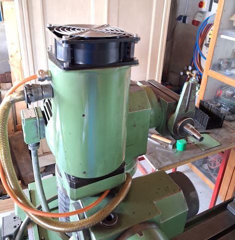
Now with the tool grinder placed at its final location, time to have some more study of the electronics. Objective is, to get the drivers turning in the XYZA directions again, and then to determine the path forward. Surely overall intention is to replace the existing PEP control computer by a LinuxCNC-based motion control system, so I can control the machine with ordinary G code and use macros and such to easily do any kinds of grinding cycles without relying on computing technology of the 80s. Also, the affordable technology at the time has been limited to one axis or two axis simultaneous movement, but we are targeting 4 axis (at least 3 axis simultaneous movement. For the Saacke machine, the Y and Z axis were controlled by an independent, TTL logic based “infeed control”, with parameters set by a number of BCD switches at the front panel. Pretty useful for recurring tasks, but hard to program special features just by BCD switches, and, of course, each grinding cycle needs to be set again by hand – you can keep the settings in a notebook but there is no way to just load a program by clicking a button. If you make one mistake on the BCD switch, rotary switch, etc., the machine will likely crash in the old days…

First of all, we need to get power to the electronics, and there is some unreliable start-up condition to the circuits controlling the mains power to the axis drivers and control section. That power is switched through contacts of the K38 contactor, which is turned on if the voltage monitoring contactor K123 is actuated, and the K124 safety contactor is actuated. K124 state depends on the limit switches of the axis, if any of these normally-closed switches opens, power to the drives is immediately cut off, so even in case of some control system malfunction, the power will be interrupted safety. There are nice slide rails, except for the Y axis, where the limits can be set by an Allen key, so that you can limit, say, the X travel to within reasonably safe limits if there are any particular fixtures mounted on the table.

The K123 contactor is actuated if all current signals (closed contacts of the X and A axis drive controls, K400 and K401 relais) and the control voltage (nominal 24 V) is good, but it also has a feature that it will not re-actuate if tripped, by the 3-4 contact pair. So, if there is any fault with motor current or control voltage, even once, the machine will stay in that state until it is power-cycled by the operator (after correcting the error, hopefully).

However, at initial switch-on of the main switch, surely there won’t be any good control voltage, and with the trip function, K123 needs a current path to switch-on at initial power-up, which is done by the K10 time relais. This device closes a contact and actuates K123 for just one second, when powered on, then, opens and stays open until the next power cycle.

It is a little dated version of still available devices from Dold Mechatronics, AI983N.7100. The inner circuit is some simple monoflop circuit, some capacitor, a relais – and, a transformer.

Turns out, there is no voltage on the transformer secondary – the primary winding is open circuit. Heavy glued to the circuit board – these devices are made to be in a vibrating factory environment, but the circuit board is of pretty ordinary quality, not through-plated.

After a quick repair – fortunately had a similar print transformer in stock – and replacement of the electrolytic capacitor, K10 is working fine, and the drives are now powering-on normally each time the mains switch is set to “ON”.

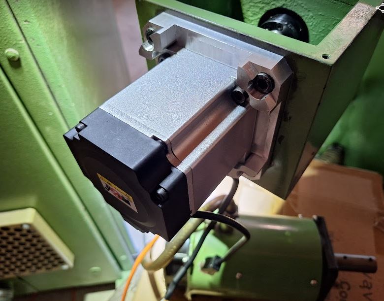
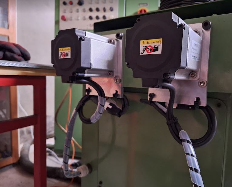
With power now established firmly, to the axis motors. The Y and Z axis (Y is moving the spindle up and down, Z is moving the spindle forth and back – similar logic to a horizontal milling machine) is driven by two independent stepper motors.

These are pretty sizeable Berger Lahr RDM51117/50 frame size 110×110 (NEMA size 42) motors, pretty expensive back in their days, and some of the strongest stepper motor available in the market.

Current rating is about 5 Amp per coil, 500 steps full step, 1000 steps half step.

Because of the lack of computing power and also lack of immediate need, there are two motors, but only one drive! The drive used for infeed automatic control is selected by some switches, including rapid functions. The current is turned off during switch events, surely, never unplug or cut the current of a stepper motor while energized – it will likely damage the driver transistor.

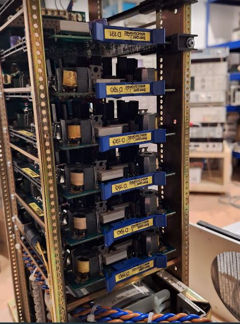
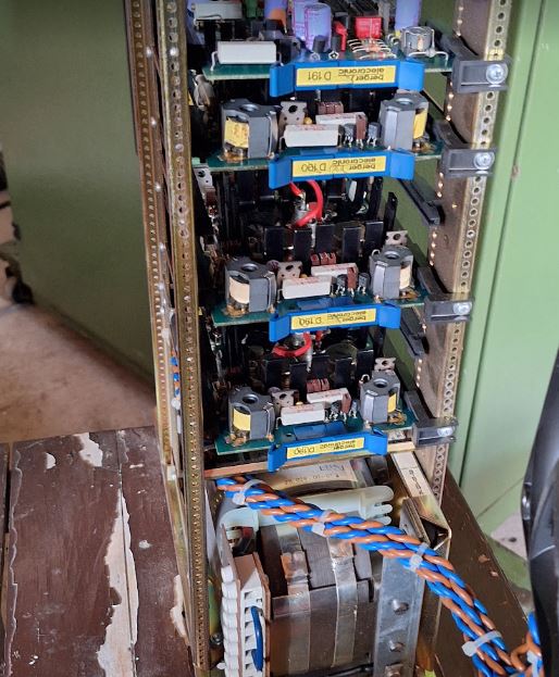
The drives are “Quintronic” NI series drives, very solid built.

Made in Western Germany – probably all hand assembled, and with one dedicated logic control board, and 5 D190 current control boards (one per coil) – powered by a 90 Volts DC supply, rated at 750 VA.

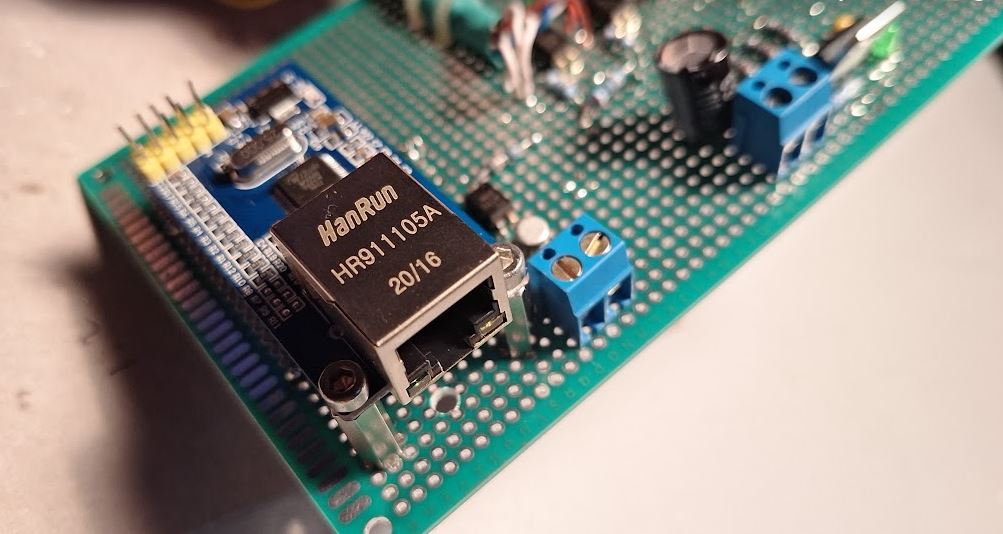
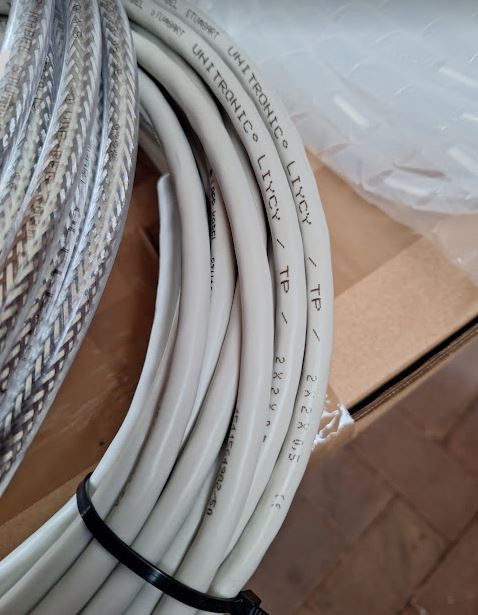
However, before being able to tests these, need to get control signals (TTL level) from the LinuxCNC PC to the old control system (running on 24 V HV-TL, respectively, open collector inputs).

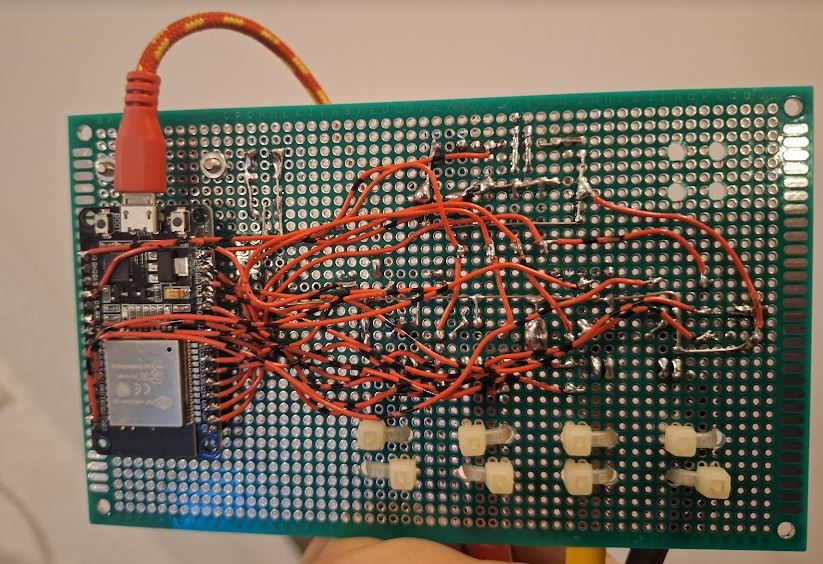
Copying some circuitry I found in the Saacke old interface, using 7406 and 7407 open collector, some resistors, and a high-voltage tolerant LM311 comparator, soldered together a small interface board providing two step and two direction signal conversion. These also connect to some counters for the A and X axis at the front panel that I may use later as an auxiliary display.

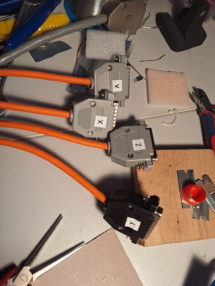
In order to select the Y or Z axis controls, I also re-wired some of the feed selector circuitry to two small Finder relais, driven by a small control board.

The control boards – no schematic even needed, just a TTL relais driver, so there is double isolation – the PC TTL level with its own ground and 5/24V rail driving a small relais, which in turn uses the 24 V control voltage of the Saacke machine to actuate the Finder relais. With such industrial controls, contactors, motors, chopper-based drives, etc., it is very critical to use low impedance noise-insensitive circuits, rather than just the thinnest unshielded wire, common power supplies, etc.

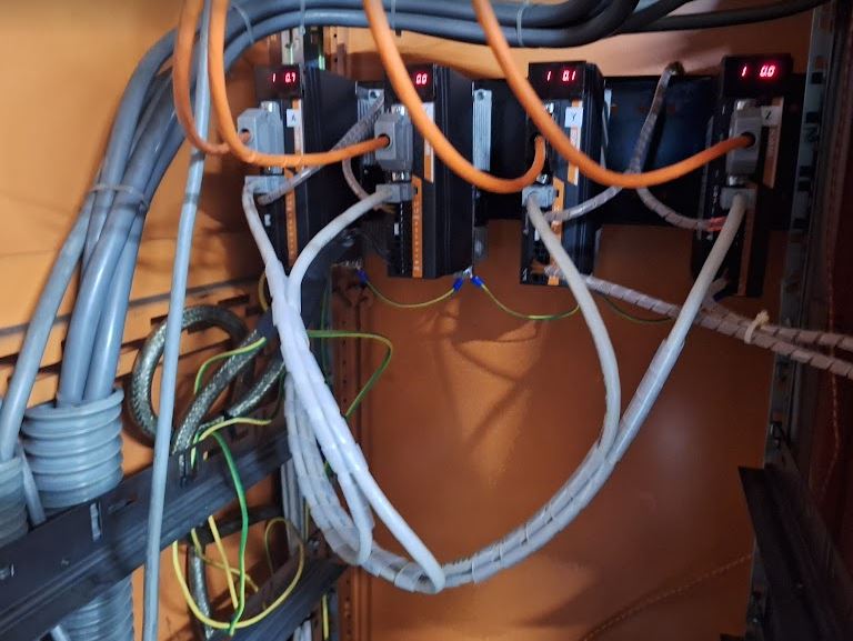
The Y and Z motors are switched to the driver by Siemens contactors K200 and K201, which need to carry the 5 Amps DC at a very low resistance, say, 0.1 Ohms, to not upset the current regulator. Coil resistance of the steppers is barely 0.5 Ohms. Generally, I would consider this a problematic setup, firstly, because the contactor resistance may not be held to these very low resistances over time, also, there is no precise timing of the current-off signal to the drives, and the switching (happens at the same time, but may be milliseconds or 10s of milliseconds misaligned). So, there may be some arcing in the contactors, etc., and eventually the contactors or the drives may fail. Upon closer examination, indeed, a different, newer Berger Lahr drive is in the cabinet, compared to the X and A drives. Likely, it had failed, and then been replaced by a unit from a different machine (still has a label corresponding to the “X” axis – the table traverse).

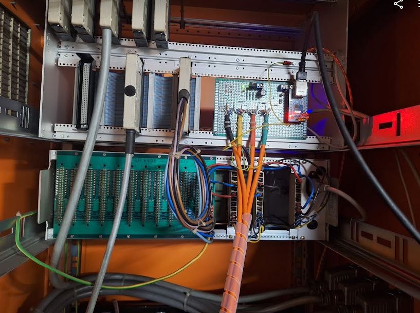
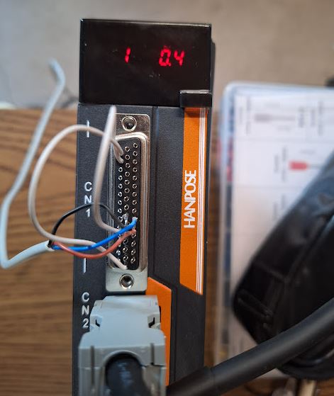
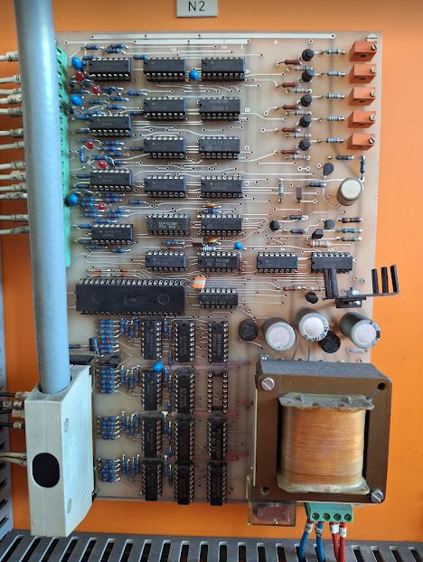
Next, the control circuit – the drives are controlled by common step and direction pulse signals, originating from a rather large card with some TTL logic on it.

For convenience, I added the new small control/level converter boards to one of the old control cards, with a temporary DB15 connector to cable it to the PC.

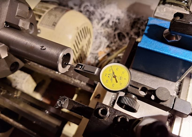
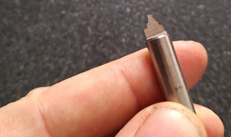
Next up, confirmation of the phase currents. The cables of the stepper motor DC supply are fortunately routed such that a simple clamp-on current meter can be used to probe the current of each motor phase without any need to disconnect cables.

The X driver had one phase at only 3 Amps of current, rather than 5 Amps, strange – the motor was still working normally. Fortunately, I have the manual and schematics (at least the schematics without values and part numbers of the circuit elements) of the D190 current regulator boards of Berger Lahr company, so it was easy to find the culprit. A tantalum cap, not shorted, but soldered with incorrect polarity. Very likely this problem existed since manufacture, and slipped through Berger Lahr’s quality control system. Maybe the tests for quality were done at a lower current, say 3 Amps, because the reversed tantalum acted like a voltage limiter at about 3.5 Volts.

Easy fix, replaced by a multilayer cap.

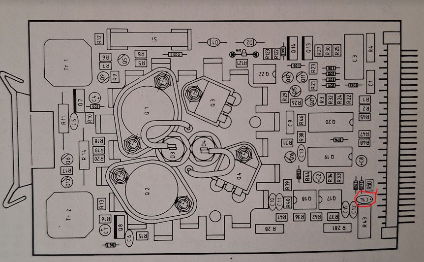
The current input is normally operated at 5 Volts, and a trimpot is used to adjust the phase current of each coil.

Unfortunately, the Y/Z driver has some problems, keeping unstable current regulation on two phases, and after a short time and trying to adjust it, blew the fuse on two of the phases.

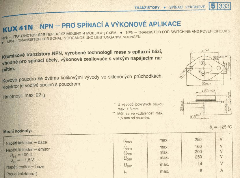
The D190 current control cards apparently used several types of transistors, I tried to collect what I can about these, some are very rare PT1132 transistors, other expensive NTE386, some use BUX41 and PT1132 in mixed (PT1132 for the upper transistor of the H-bridges, BUX41 for the lower). Nowadays, we would design that with MOSFETs and some high side drivers, easy enough.

The PT1132 seem to be related to BD245 or similar, or BUxxx series transistors, like, BU426.

Surely, we need NPN transistors with reasonably high gain, to avoid overloading the high-side drive circuit, and rather high voltage resistance (because of the 90 VDC), and fast switching – because the transistors won’t be able to sustain the linear load region to the 0.5 Ohms coil resistance for any length of time.

Later, it seems, Berger Lahr used BUX41 a lot, 200 V, 15 Amp NPN.

Yet, another type of BUX41…

NTE386 devices, very solid devices, but expensive, more than 20 EUR a piece!!

Finally, I would like independent motors and controls for both Y and Z, to avoid complicated switching and programming, and surely no full-current switching between driver and motor – surely retire the K200 and K201 contactors.

The are some options,

(1) Repair the Berger Lahr D190 cards – will surely repair these after sourcing some BUX41, but this will need to wait for some winter days and less busy times. Even consider to modify the H bridge on the card, by using MOSFETs and modern drivers. The drivers I have have combinations of PT1132 with BUX41, and PT1132 with RCA 41013 (equivalent to BDY58, NPN 125 V – 10 Amp, current gain of at least 20).

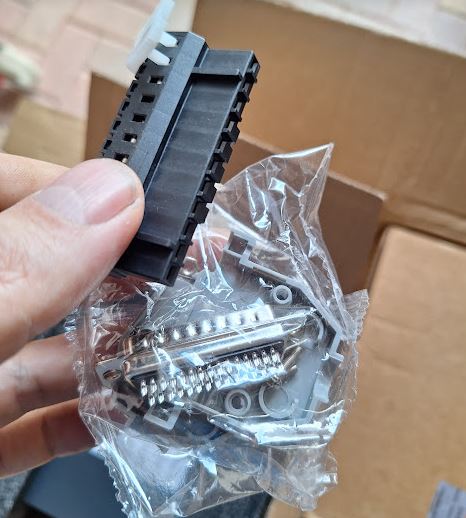
(2) Replace the 5-phase steppers by some NEMA42 bipolar steppers, with conventional microstep drivers – easy to maintain and repair going forwards. Then I would have some spare control cards from the former YZ driver, should any cards of the X and A axis drivers fail.

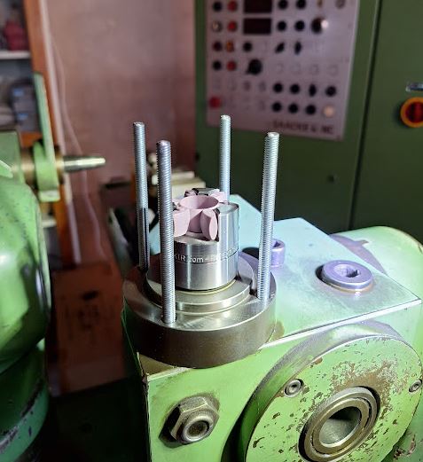
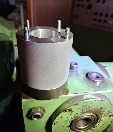
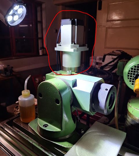
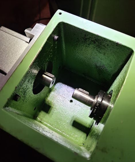
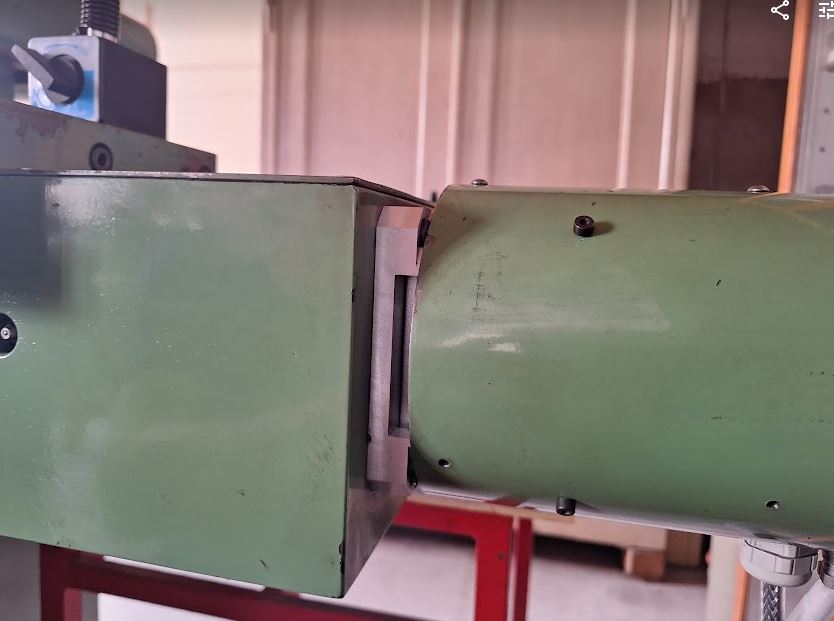
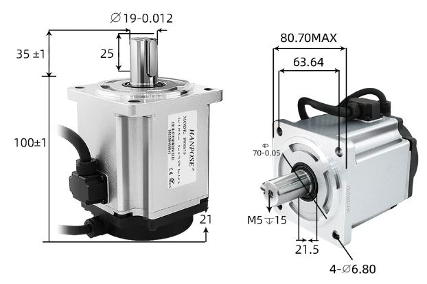
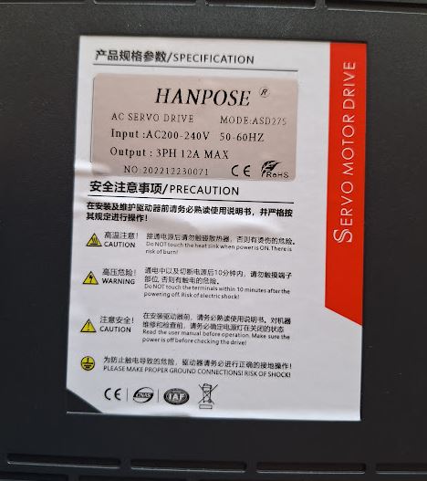
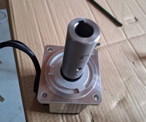
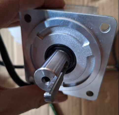
(3) Consider using more modern drive topologies like AC servos with encoders for the Y and Z axis, even for all axis, one I have figured out necessary adaptions of drive geometry (shaft diameters, case diameters).

With all the troubles of the design and state of the Y and Z drives, the X and A axes are working very well, even with the dated drivers and motors. 1000 steps per revolution results in about 3 mikron per step, and the speed of the table can easily reach 500 mm/min and more (mostly limited by the maximum step speed of a LinuxCNC real time step generator over parallel port) – given that it has a ball screw and roller ways, the mechanics would certainly tolerate more without any problem. Also confirmed the very smooth action of the table, mechanically no problem at all with the machine. Also the Y and Z axis – mechanically – are very sound. Cleaned all the screws, guideways etc., from the black dust and grease (better not use grease on grinding machines, but some CLP or HLP 46 oil).

Tool Grinding Machine Saacke UW II NC: a few basic repairs

The next big task, moving the Saacke from the entrance area of my house, to the workshop building. Fortunately, there are no stairs and steps, essentially, flat ground, but moving a large 300 kg electric cabinet, and a 700 kg machine, it is no easy task if you don’t have the right tools

Eventually, with the help of a friend and a pallet jack, maneuvered it to the location, but getting the pallet our from underneath a the machine, difficult. In a large factory, you just lift it up by crane of forklift, pull out the pallet, and let it down slowly. Also, you could build a tripod or gantry, and use a hoist to lift it up, but it is all pretty dangerous and labor-intensive, because I don’t keep all kinds of structural steel here.

Eventually, I managed to tilt the machine enough with a small hydraulic car jack, put two heavy flat steel bars underneath (70×15 mm), and lifted it up on some wooden support alongside the pallet, just suspended about 5 mm above. This way, I could pull out the pallet, and then lower the machine done bit by bit, by tilting it, and lowering the support 1.5 cm at a time, to avoid undue tilting. Take care that the whole thing doesn’t shift, and keep you fingers and feet clear at all times!!!

Eventually, after about 2 hours, the machine is at its final place. I will probably screw it down with three bolts, so it won’t move after setting it exactly (I mean very exactly) level. It makes it much easier to work on an exactly level machine, because you can use an electronic level to adjust angles pretty accurately. The seller did take great care of packaging the cables and plugs, glad these were not damaged in transit, because fixing these plugs normally means to completely newly wiring them, and while they are still widely available, these industrial plugs don’t come cheap.

Now, to some basic repairs, to fix the damages inflicted on the machine during transport.

First thing, a wheel of the electric cabinet (which has 3 doors, so to open the doors, you need to move around the cabinet. One wheel completely broke, probably someone hit it onto some wall when loading the truck. Rather than buying 4 all new wheels for such old machine, I try to fix what I can from stock I have, rather than buying ready-made parts. After all, that’s one of the purposes to have a workshop rather than a warehouse full of spare parts.

I cut-off a piece of a 35 year old rod of polyamide that I had around since my childhood time, once found at a scrapyard… then some machining on the lathe, and, a very study wheel is ready and mounted!

The fan of the table (X axis) drive, it really got damaged severely, fortunately, except some wire damage, the motor cover prevented further damage to the drive system, coupling, and, the very expensive ball screw that drives the table.

Most of these fans have their connectors at the outside, but the original one had been cabled to the inside of the cover. At least, I found a good replacement fan 112 m3/h nominal air capacity, run directly from 230 VAC mains.

Some disassembly of the connector, to get the wires exposed, some drilling.

Some soldering, shrink tubing has glue inside.

Still some need to adjust the cooling covers, but finally, got all the cables mounted and fiddled through. Also removed a few spoons full of grinding dust, and other dust.

Both the X and A (rotary) axis drives have new coolers.

Looking good, but the drives don’t even get that hot.

Next thing up for repair, the cover of the table.

Really terribly bent, taking it off was no easy task, drilling out one of the screws and taking great care not to damage the table.

To straighten it out, it took some patience, a vice, a polymer hammer, some pieces of wood.

Bending carefully, hammering it with quite some force, it is no thin metal but a pretty solid sheet. Amazing how crudely the carrier handled the shipment.

Some more knocking and bending.

Eventually, cleaned the plate and mounting surfaces with engine cleaner, still having some old cans around, but ordinary petroleum also works, and doesn’t attack plastic.

One great addition to the machine – a very nice German-made adjustable high-precision grinding vice, gifted to me by a relative. The vice has some little rust, but I will give it a good polish before using it on the grinding machine.

Tool Grinding Machine SAACKE UW II NC: “the small one” arrived

Over the last several month the electronic workshop has suffered from little work with test equipment repair, I think, we have an economic crisis – nobody seems to be interested in keeping their old equipment going, if even the new equipment is idle. More time to spend with traveling and other tasks, including, finally getting a new tool grinder.

For the fabrication of microwave components, like, mechanical filters, test antennas, etc., I am using custom-made tools of HSS (high speed cutting steel), mostly the parts are made of brass of Ni-Cu(-Zn) alloys, so HSS tools are superior for precision machining, compared to, for example carbide tools that don’t hold a sharp edge well.

Usually, we are considering small cutters here, 6, 8, 12 mm diameters. A radius tool, for example, for internal turning or single-edge milling.

…precise angles must be kept to keep the cutting edge going.

Also, for very tiny pieces, with complicated internal features, single point cutters don’t work well, so I need to resort to strong, custom made step cutters. Note that the shapes are calculated according to electric requirements, but the practical fabrication needs tests and adjustments, and eventually, repeatability, to get good results. Otherwise, the parts will randomly scatter in performance and it is hard to make a set of, for example, 3 pieces, without making 10 pieces scrap, with all the wasted time for machining and, especially, testing.

These tools can be cut by hand on a so-called cutter grinder, earlier introduced by Deckel company of Munich, model “SO”, but now available as import from China, at quite reasonable quality and cost (still, about EUR 1000).

While this little marvel is working very well, it demands outmost focus and consideration when grinding cutters, and is very time consuming to use. Re-grinding tools reproducibly takes practically the same effort than just making a new tool – all angles have to be set again, and all at the same risk of error and misoperation.

In effect, I have been using tools even when a little bit blunt, at a loss of surface quality, burrs (which are extremely bad, because we cannot polish these electric precision parts without destroying the precision, and burrs do show up in refection coefficients and gains).

A solution – we need to get computers and controls involved, in short, CNC. Buying a good CNC tool grinder, 4 axis to also be able to cut and re-sharpen gear cutters or mill cutters, will set you back at least 100 kEUR, including various expensive software options and difficulty in keeping it going without a service contract.

So I have been shopping around for a more affordable option – buying a solid heavy mechanical machine suitable for retrofit (for example, adding a new motion controller – using LinuxCNC on my other machines, fixing some electronics, replacing some or all of the drives and axis motors; but using all the existing mechanical system, the existing grinding spindle, etc.). This search has been underway since last year August, and after finding a machine, even paying, the seller damaged it so badly in his warehouse that he returned the money, still, no machine for me. Eventually, I found this very interesting machine, Made in Germany in the 80s, based on one of the best and solid designs of a manual machine, the SAACKE UW II. The main features are (hardened) roll-bearing supported long table with ball screw, tapered roller bearing A axis (heavy enough for milling), and prismatic cross-slide (trapezoidal screw) on wide-spaced support, along with a 1 mm-per-turn Z adjustment (high precision worm gear).

The introduction of the machine, considered by SAACKE as “the SMALL one”, no less than 80000 DM in 1985… probably equivalent to 90 kEUR today.

The 1 kW spindle is by far enough for the purpose, the machine can also cut very large milling cutters, flat grinding and round grinding (also tapered grinding) is all easily possible because of the 900×140 mm table.

Having found the machine at a reputable dealer in December 2023, it took several month until I could actually buy it, eventually, got it for very reasonable money, just about 2 EUR per kg, shipment included!

It arrived on two pallets, well secured and packaged. But with some parts sticking out. Already in phone conversation with the seller we had the concern of damage, but there was no practical way to transport it here at reasonable effort, rather than just giving it to a commercial carrier on pallets. Surely, I would always suggest you have your machines point-to-point delivered, even drive the truck yourself.

The transport took more than a week, and the carrier probably loaded and unloaded it several times from the truck, eventually, inflicting various damages to the machine. Fortunately, they didn’t drop it altogether.

A broken fan, a completely broken and ripped-off side plate, a broken roller, etc.

Quite some effort to disassemble the parts, find replacements, etc. – commercially, hard to fix, but we are talking about a major retrofit and modification anyway, so we can do it step-by-step in the evening and on (rainy) weekends, not counting all the hours.

One great plus of this machines are the full manuals, even of the motor drivers (using Berger Lahr 51117/50 stepper motors, really big ones!). For some control boards, and the PEP computer (the old brain of this machine), at least connection diagrams.

The main electrics of this machine, very nicely made in a general control cabinet, with all high quality contactors and fuses.

The cabling and connectors are all of the highest quality, costly, heavy duty German-made design.

The old control boards, in a nice rack. I am planning to use the existing motors for the table and A axis, the cross-slide and Z (which has one shared driver), haven’t made a decision yet, will just get it working for test reasons I believe.

The feed of cross-slide and Z is done by a feed control system rather than the 2-axis control (table X and rotary A axis that is controlled by the computer, coordinated motion to cut spiral flute cutters).

Soon will power it up. Just a note – this machine didn’t have ground connected, but wired as PEN connection, with a N-PE bridge. So it needed some testing of isolation (which it easily passed), and has already grounded 220 VAC and 24 VDC control voltages (adjusted the tap to get the voltages down a bit – design for 220 V, but I am getting about 230-233 VAC here). So if you get into such adventures with old machines, please make sure to contact someone knowledgeable about electric systems, don’t just plug it in!

Next up will by a study of the motors and drivers, some cleaning, some tests of the mechanics (have some precision granite square here to check for any wear/perpendicularity, and a high precision encoder to check the A axis).