Not giving up on the HP 8753C Network Analyzer repairs. Especially, because these units are really top class in terms of specifications and serviceability, easy to use, and well handled by GPIB bus software. Not sure why you would by and later model, if you have a working 8753C or similar model.
Some study of the YIG oscillators used in the 8753 series analyzers, while these are nothing special neither in output or tuning range (3.8-6.8 GHz, and a quick test on the source assembly shows that everything above 8 dBm seems to drive the source mixer to saturation), they have a ~23 mA/GHz tuning current, much less than the 50 mA/GHz (20 MHz/mA) of many industry standard and common YTOs. No idea why that is, a bit less power consumption, a bit less copper?
Looking around, found this marvelous Watkins-Johnson YTO, for just about 15 EURs. It was a bit dirty with wires badly soldered to it, but easily cleaned up.

Power is good, measured through a 6 dB attenuator, and pretty stable all over the range (won’t even need it up to 8 GHz).
a href=”https://simonsdialogs.com/wp-content/uploads/2020/02/8753-yig-replacement-power.jpg”>
There were no data on the power supply, so I needed to test it out. Heater voltage, seems to work well with 15 Volts, supply voltages -5 and +12 V give stable operation with sufficient margin (there seem to be internal voltage regulators).

The tuning current 50 mA/GHz, about double of the 23 mAh/Ghz of the HP YTO. So, there will be more heat dissipated, let’s do some calculations around the YTO driver. Located on the A11 board.

Clearly, the transistor will have to dissipate more heat. Do avoid any big changes, let’s adjust the current sense resistor to about half the value – resulting in about the same voltage drop per GHz.
The driver transistor, nothing special, a NPN TO-3 part, used without a heatsink.

There is no good space to fit a heatsink for TO-3 transistor, so I replaced the transistor. Used a BD245C, with amplification hfe of 40, well good enough. The SOT-93 case, it can easily be mounted on a piece of sheet metal (aluminum) to provide enough cooling.
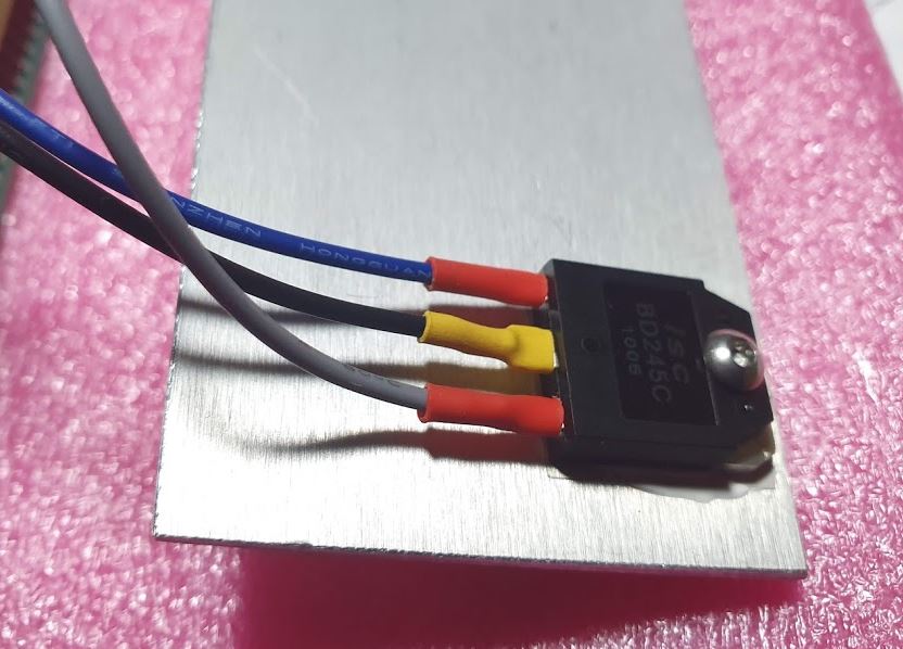
Everything well insulated and mounted. Using the TO-3 screws to hold the transistor/heatsink assembly.

The current sense resistor, the key part for any YTO driver, needs to be low drift, low thermal coefficient. Otherwise, there will be all kinds of drift. HP use in some of their equipment sense resistors specified to 2 ppm/K, the best I could get is about 15 ppm/K with Dale RH-10. One day I will check their actual thermal coefficient. Now I just burned it in a bit, and selected one that looked perfectly stable with any load changes up to 1 Ampere.

The A11 board can be modified fairly easily, even reversibly – replace the sense transistor, from 40 Ohms to 20 Ohms, cut a trace (the current sense voltage to the opamps, close to the board connector – the via is handy to attach a wire). And a 18 Ohm/390 Ohm/200 Ohm -10 turn pot arrangement to set the proper currents.

Another small modification, the 1 k/100 network across the main coil – replace the 1 k resistor by 2.2 k.


The 8753C provides +15 V and -15 V at the YTO connector. Assembled a small power regulator board, to provide the necessary +12 V and -5 V.

Testing…

Several adjustments of the 10T trimmer, but there are issues – no stable lock below 3.3 MHz, and the Service Function 58 won’t do the pre-tune corrections. Note that you can use the source tune mode to monitor the YTO with the PLL disengaged. Ideal for adjustments of the YTO slope. Still no stable lock. Working reasonably stable at times, but all a bit temperamental.


Various lock issues, and the self tests won’t work well.

Some study of the manual, and quite some time spent to add more components, changing PLL filters, and so on. But no luck. Below 3.3 MHz, there is a also a gain change of the PLL, by Q10 FET, also modified a bit there, some improvement, but not as stable as it needs to be.

Maybe, some specific issue of this YTO, at least after detail study of the tuning currents, some magnetic hysteresis, or similar. Not an uncommon problem. Not all YTOs are suitable for fast, precise sweeping and phase-locked operation.

After all, let’s give it another try, with another YTO. Found this beauty for USD 25, a great AVANTEK YTO, ASF-8347M, with solid output power. Hermetically sealed, in a magnetically shielded casing.


