With the basic installation of the servo motors complete, still some work to connect all the motors and encoders solidly to the controllers inside the (massive) control cabinet. First, wiring the cables through the base of tool grinder, a heavy iron casting. This casting is made of a rather hard type of cast iron, difficult to drill larger holes by hand tools. So I tried to to re-use existing plugs and connectors as much as possible. While for the power connections, there are plenty contacts of the big industrial connectors and cabling available, for the encoders I wanted to use twisted pair cable and plugs that are physically separated from the power cable feed-throughs and plugs.
Shopping around, I found these Aliexpress plugs, from China, but with good IP rating, IP68. The cost is very moderate, and the size “SP20” happens to fit the openings and screws of the former fan power connectors.
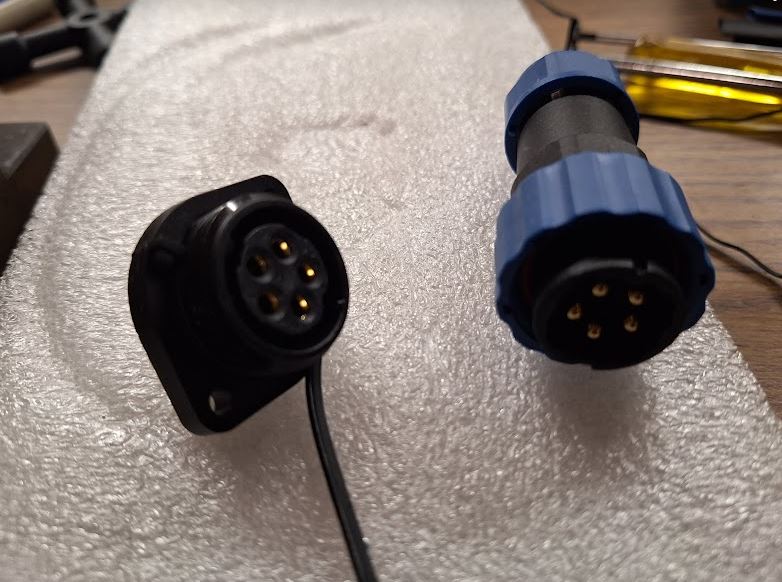
Fortunately, these connectors arrived quickly and there was no need for any modification of the machine base.
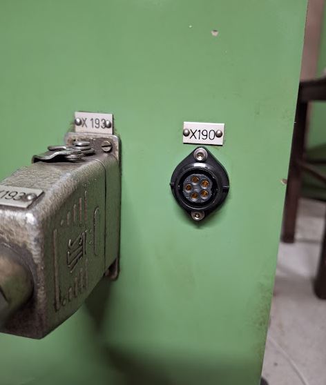
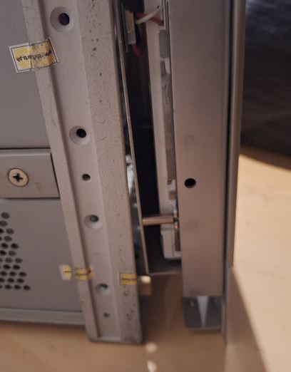
To guide the cables of the encoders (total of 4 cables, 2 twisted pairs each), there was not enough space in the existing duct. So rather than wasting time with pulling heavy cables, I just decided to add another duct from the machine base to the control cabinet, dedicated to the encoder cables.
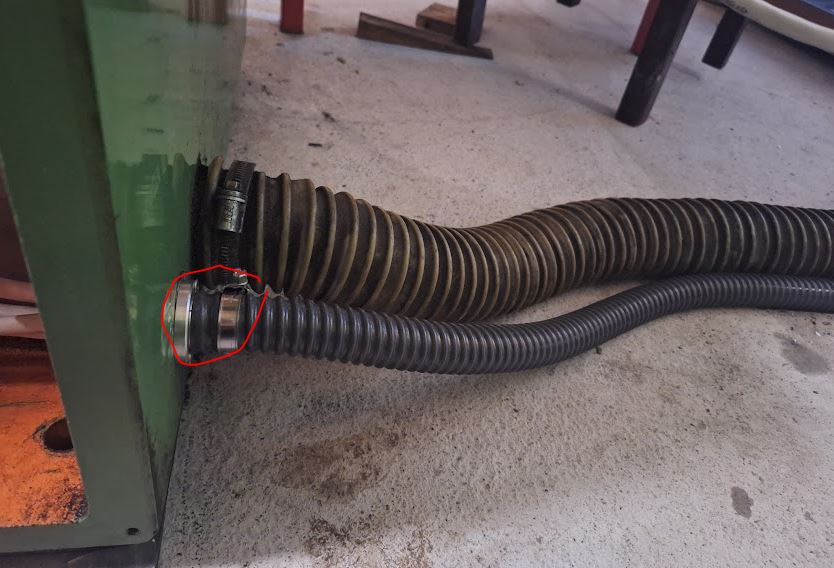
Installation was not easy – drilling a sizeable hole in the machine base took quite some effort, but eventually, the cast iron could not resist a sharp Cobalt-alloyed core drill.
Next, some important work inside the control cabinet. After removing all the old controls and motor drivers, there is now ample space available, but all we will need is a 160×100 mm board, and even that is mostly needed to connect all the cables.
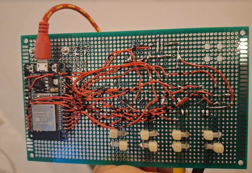
Key part is a ESP32 board, which does all the heavy work, on the other side, a W5500 ethernet interface, connected through SPI.
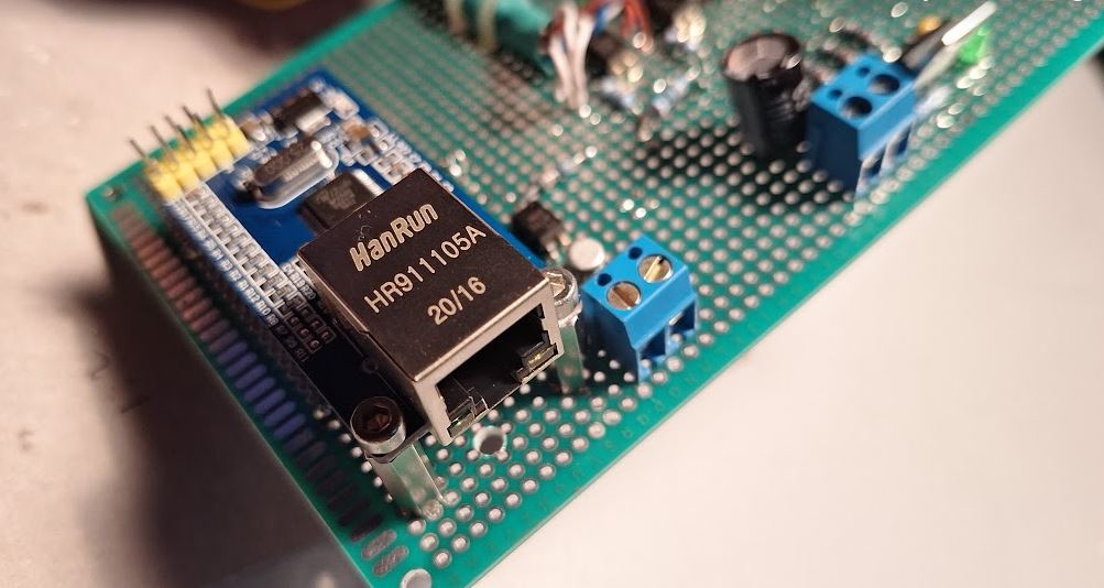
The soldering went faster than I thought, and the board is now mounted to the frame of the old control system. All powdered by a single 5 V power adapter (and an on-board 3.3 V regulator).
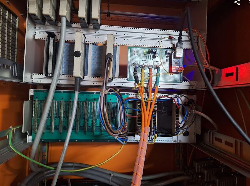
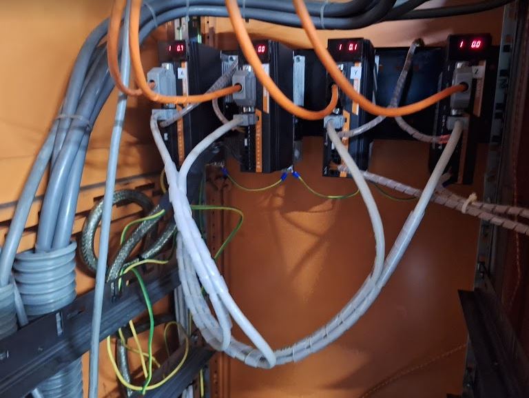
More time consuming that was all the other cabling, each of the controller has a 50 pin high density D-sub plug, with the fault, step and direction signals. I used some twisted pair (CAT) cable to make the short connections from the servo driver to the ESP controller.
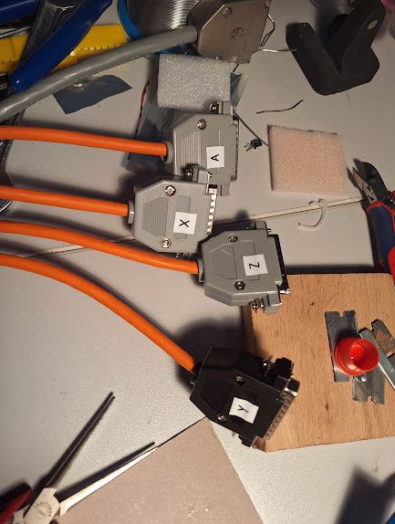
At the driver side, it now all looks neat, and also the connectors of the encoders were cabled with IEEE1394 (SM-6P) standard. Lots of work with tiny wires, heat shrink tubing, etc.
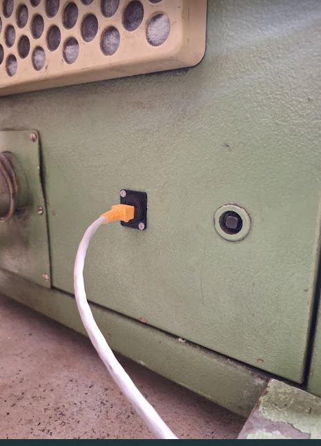
Finally, I mounted a CAT6 panelmount connector, so the whole grinding machine is now controlled by one ethernet cable, running UDP protocol.
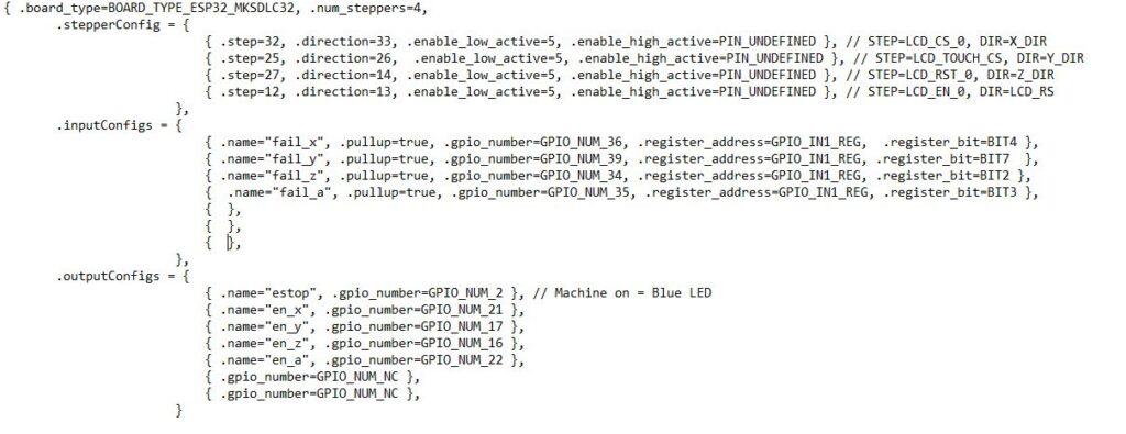
Key part of this is the software, and while I have other machines running with (expensive and – in Europe – difficult to get) MESA cards, this time I resorted to a public domain development found on Githup. A really great project there. I managed to get some bugs removed and to make it work for my needs with 4 axis and one ESP32. The pin layout is quite critical, because the signals and the ethernet SPI will basically require almost all outputs of the ESP32.
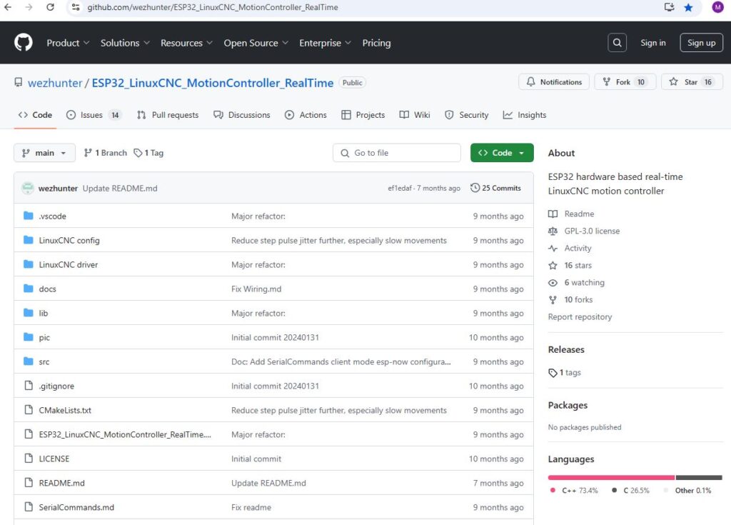
Some issue existed with the configuration, so I decided to hard-code the pins. Anyway, for now it is the only machine I have to control by this ESP32 motion control software, and there is no problem to customize it directly in the code.
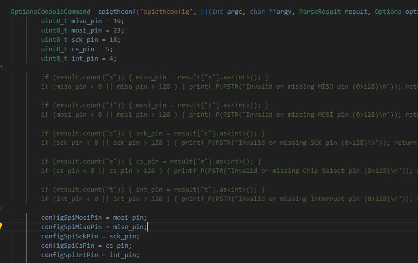
For those interested in detail, here is the port layout.
As before, the motion control will happen through LinuxCNC, with a HAL driver that is talking to the ESP32 through UPD updating the motion commands every few milliseconds. All the step generation and time-critical motion control tasks are done directly in the ESP32, so the communication between the LinuxCNC and the ESP32 is not that time critical. I won’t describe all the driver tuning and LinuxCNC configuration here in detail. Drop me a line if you are interested. Probably I can get you started on some own projects.
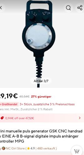
From Aliexpress, also another part arrived – a handwheel – rather low cost but good look and feel. This will be connected to a parallel port, because there is no time-critical events there, just reading the signals and linking them to a software quadrature encoder in the LinuxCNC HAL.
