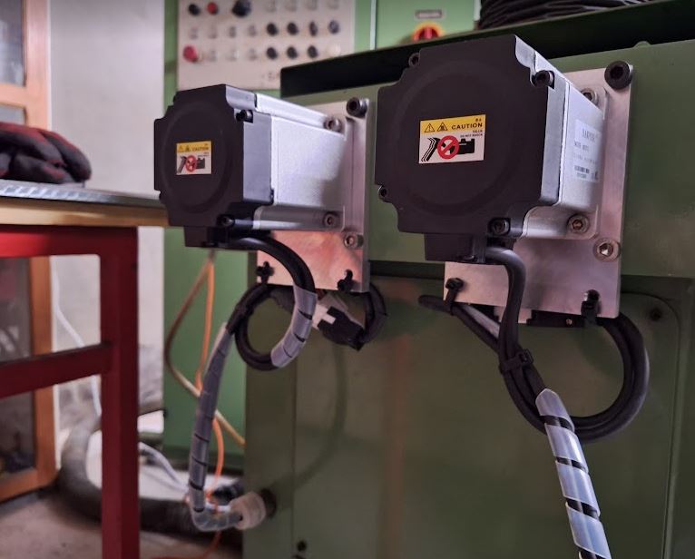
Tool Grinding Machine Saacke UW II: fitting new servos to the the old machine (A, X drivers)

For the X (ball screw driven left and right) and A (rotary) axes, now as the servo motors have arrived, we need to find a way to mount the servos to the existing drive mechanism. My intention is not to modify any of the shafts and precision parts of the Saacke machine, but to determine a way to mount the servos with high precision of axis alignment, and a coupling that can transmit the torque without slop or delay.

The mechanical parts and brackets, I decided to use aluminum alloy rather than steel, even Saacke manufactured the stepper motor mounting plate for the A axis from aluminum plate, and the strength will be good enough, with no need to paint or oil the necessary adapter plates.

The couplings, I used KTR Rotex, size 19, with 92 Shore TPU elastomeric couplers. These were available already machines to the right size, including matching keyways. Found them used, or old stock, a good deal.

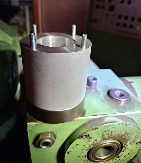
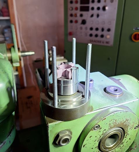
To house the coupling, made a cylinder from aluminum alloy, and 4 holes drilled for draw-bolts. The draw-bolts screw into the A-axis head, and nuts will be used in the servo mounting plate to hold things together.

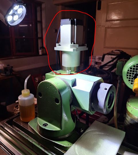
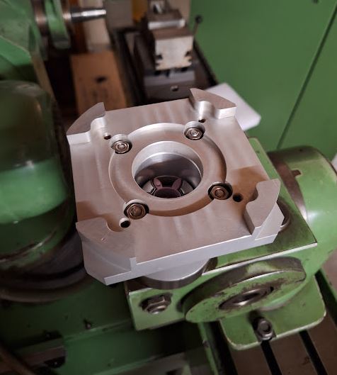
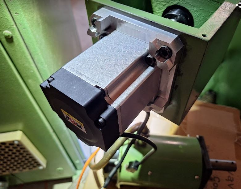
The servo mounting plate required quite some planning to match both the machine side, the servo flange, and the fan cover (which I plan to re-install to protect the servo – the cooling fan doesn’t seem to be required).

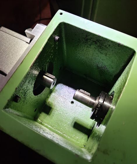
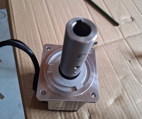
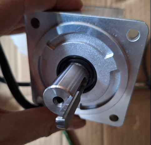
For the connection of the coupling and the head drive, made a rod with a long key slot (formerly, the long shaft of the stepper motor was directly fitting into the A axis drive head.

Fortunately, all the parts fit right away, torqued the draw-bolts carefully, and adjusted the couplings for proper clearance. There was a little slop in the coupling, so I bent some thin shim stock to pre-tension the polymer coupler a little more.

The distances and plate thickness was designed such that there is enough strength, without adding to much weight or unnecessary stick-out.

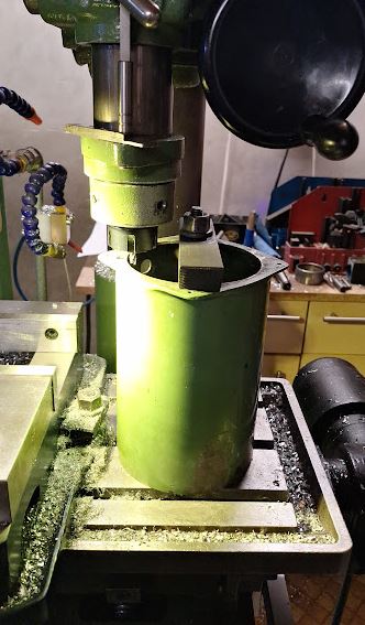
The fan cover, steel, had some other fans originally that you damaged during transport, and the adjustments for new fans were done by hand before, now a good chance to clean these (grit and dust filled) covers (there purpose was to direct the fan air around the stepper motors), and to mill out a little more space for the cables.

Handy to have the manual mill, and various workpiece holding.

With the cover mounted, all looks nice and neat, and overall a few kgs lighter compared to the former stepper motor. The cover is held in place by 4 screws, radially arranged, that have steel (stainless) spheres pushing onto the servo.

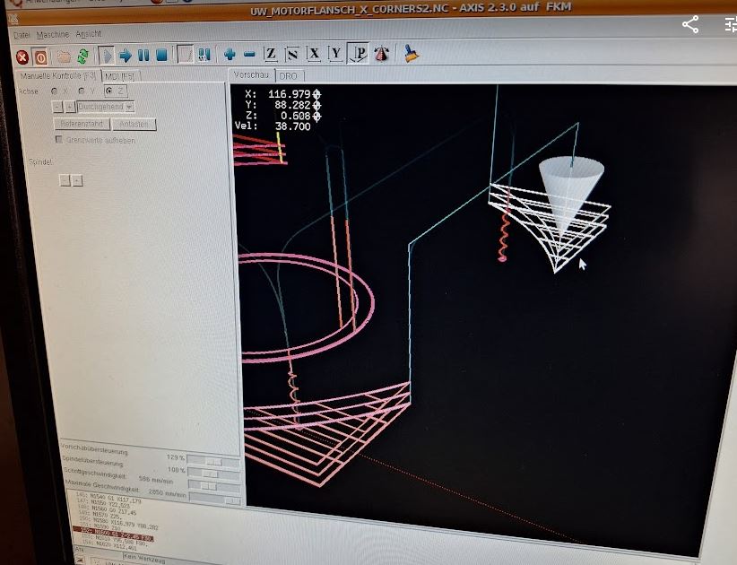
For the X axis, similar case, programming the CNC code, milling the aluminum plates. These mill jobs took a little while with some many features, but no purpose to optimize the program for a single piece.

There was no need to drill new holes, the plate was made such that the existing stepper motor threaded holes can be used.

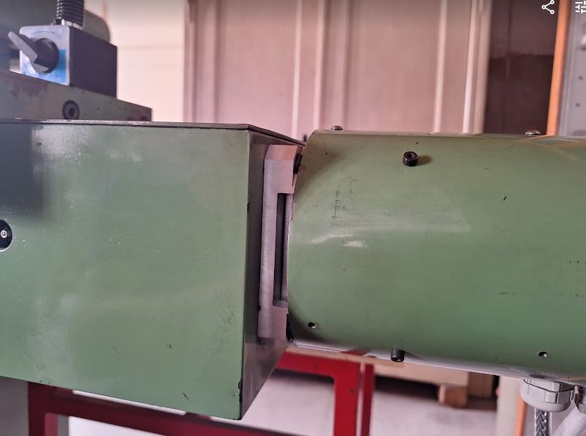
The spindles shaft and the servo shaft have different diameter and key size, but also here I was able to find suitable KTR Rotex couplings.

With the cover, it looks like not much has changed vs. the stepper motor, and there is still enough space for the cables (drive cable 3 poles plus ground and encoder cable – 2 twisted pair plus shield).

With all the work on the X axis, I used the chance to clean the screw bearing thoroughly, and adjusted the ball screw precisely (with a micrometer resolution dial on the table, and checking the pre-tension), but also found that the bellow cover is was badly worn, full of grease and dirt.

Finding a replacement bellow cover, from the original manufacturer, a German company, I was not even able to get a quotation, which would likely be cost-prohibitive anyway. Looking through Aliexpress, found a very cooperative supplier in China – this company provided a custom made cover for just about 30 EUR, shipping to Germany included (no customs to be paid). They were not able to provide small “tabs” at the side to hold the bellow cover in place, therefore I cut some from PVC plate, white color was the only thing I had available – but it will not be visible once installed anyway. Using special PVC glue, which really softens the plastic and welds it firmly, these plates were attached with very good strength. Also made a test piece, and could not actually break the glue joint without destroying the whole piece.

Installation of the bellow cover was easy – some small brackets and 3 screws each side, and the dimensions fit well. The material of the Chinese supplier seems pretty durable, oil and solvent resistant material, and many PVC frames (in each fold) to make it stiff and keeping shape. Let’s see how it will perform over the years.

Tool Grinding Machine Saacke UW II: steppers to servo motors

Some more work on the Saacke, the original design had 3 motor drivers for 4 stepper motors – the Y and Z axis being operated by one drive. My original plan was to get another stepper motor driver, but for these 6-phase high current steppers, not an easy thing. While there may be some old controls available, they are pricey, like 1000 EUR and more. Also, I was not too thrilled by every year repairing at least once the driver – 30+ year old electronics doesn’t normally provide a particularly high level of reliability.

Another choice would be to replace the RDM-51117 steppers with some other (2-phase) stepper motors, but rather than 1000 steps per revolution that would result in only 400 steps (half-steps) per revolution, or not very precise micro-stepping. Not good, because the Y and Z pitch is 1 and 3 mm/rev, respectively, and a grinder normally should be controllable in 1 mikron, or smaller, increments.

Analyzing the torque requirements, I had the idea to use a servo motor instead, because the holding toque requirement is actually pretty small (the feed screws turn easily, and once at position basically no force needed). AC servos (with an encoder feedback loop) have become affordable in recent years, why not use one of these?

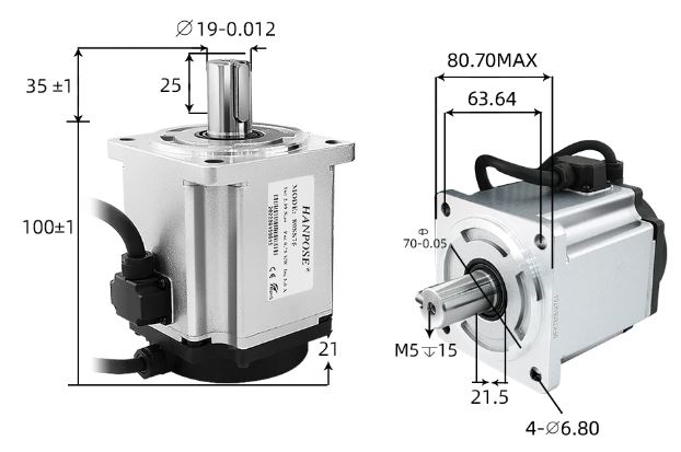
Shopping around at Aliexpress, I found these 80SS75 (750 W) AC servos, offered including drive and 3 meters of encoder and power cables. Available from a Chinese vendor (Hanpose), ready to ship from a Belgium warehouse.

Chatting with the sales manager a little, the lady offered my a very good deal, almost too good to be true – so rather than buying just one motor, I ended up ordering 4 sets, and decided to replace all the stepper motors by servos.

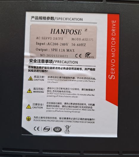
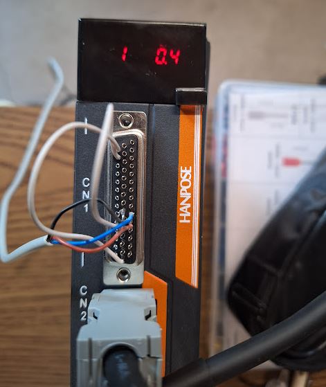
These servos come with ASD275 drivers, these are quite similar to other AC servo drivers I have used before, they all follow similar programming and characteristics. One important characteristic is that these drive need tuning of the control loop once installed.

Only a little wait, then 4 boxes arrived – all stuck together and wrapped in plastic, not bad!

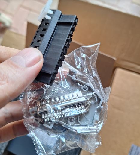
These sets include not just the cables but also the connectors, great! Full sets! Even an English manual is available.

Some mechanical differences exist, so we have to make adapter plates, and modify the couplings. The Saacke design has just hard-coupled drives, there are no fancy parts, just a steel sleeve. This works well when all is centered up correctly.

Also the key had to be modified, because the sleeve has a 5 mm keyway, but the AC servos have 6 mm keys. So I milled away half a mm each side, to make it fit.

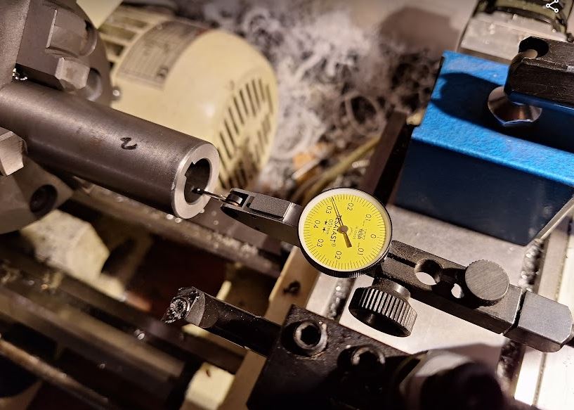
On the lathe, I used great care to center the sleeves precisely, to avoid excentricity.

Turning it to a larger hole diameter was easy, and a great surface finish.

Before fitting the motors to the machine, I did a quick desk test, and all working fine, out of the box!

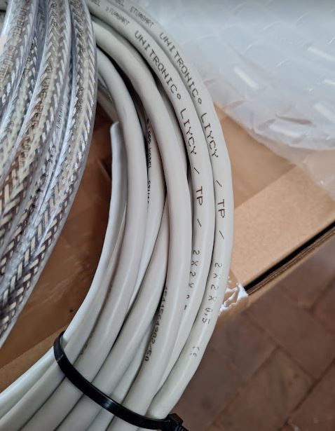
For the cabling from the machine to the control system, I selected LiYCY-TP (twisted pair) cables, 2x2x0.5 mm2, for the encoders, and Lapp Ölflex Classic 110 CY (shielded) 4Gx1.5 mm2 control cable for the power drive. These are a recommended and cost-effective solution for all kinds of servo and stepper cabling.

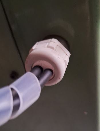
The motors were easy to mount, and the cables installed in the machine – a little oily and dirty task, but also a good opportunity to give the Z axis guides a good clean. Luckily, I had in stock 2-cable feedthrough plugs from a project about 30 years (!) past, from my childhood days! Now finally I can use these for the grinder….

The adapter plates were quickly milled on my CNC machine, all with great care for perfect centering. For efficiency, I used AlMgMn alloy 5183, which is easy to machine to high precision and practically free of warping or internal stress.

Installation went smoothly – a little tight fit of the motor flange, but hopefully, this will be a one-time installation.

The motors are rated to 5 Amps and more, but as expected, the typical currents are just around 1-2 Amps when moving, and 0.3~1 Amp when stationary.

Next will be modification of the X and A drives.

Heraeus K1150/3 Oven: some cosmetics, some bricks, some electronics

There is always some need for heat treatment in my workshop, for example, hardening, softening, tempering of steel, hardening of aluminum alloys, etc., often just done with a torch and by visual judgement and feeling more than measurement. While this works for small parts and general tool steel quite well, it doesn’t work for hardening of aluminum (precipitation hardening), and larger pieces of steel may crack. Even smaller pieces may suffer from uneven heating, resulting in distortion.

A small electric oven is handy for that so far, a German brand, “Naber”, already pretty dated but it seems to have been very rarely used. Not long ago, added a controller, to allow curves and automatic controlled heating and cooling operation.

But recently, screening to classifieds, I found a much better oven, 4-side heated, Heraeus K1150/3 that can handle much larger pieces for heat treatment.

It came pretty quickly, for just a little over 400 EUR, including delivery and including a cart. First thing I did, painted the cart a little with red paint – RAL3000 “feuerrot” as it is called officially. For years I carried around a can of such red paint, never thought I would ever actually need it.

The oven, it can operate of 3 phase power, 380 V 14.5 Amperes, originally. Now with a mains voltage of 400 V, the power will be about 10% more. In any case, I can connect it to my 16 A outlets.

The oven has quite significant heating power for its size, good for heating up metals quickly, for hardening. Also, it is built such that it can be opened pretty safety in hot conditions, to take out the glowing parts – not all ovens (especially not common pottery ovens) can be opened when hot – the refractory bricks may brake, or the coils may bend, or similar.

The next difficult task was to get the oven back onto the cart, not easy, because of its bulky size and well over 100 kgs of weight. Even with 3 people, impossibly to carry, and not easy to grab. But with various pieces of wood, some small furniture rollers, eventually managed to get it onto the cart with the help of a friend, and no damage or injury!

The bricks of the oven are all in good state, except for some loose parts at the front door. There, the inner (hot) layer is held to the door by 4 metal parts.

With refractory glue, stable to well up to 1100°C, and easy to use.

To do a proper job, I cleaned up all the old cement, and thoroughly roughened the mating surfaces.

By the manufacturer, the oven has a very sturdy Pallaplat (Au-Pd-Pt vs. Pt-Rh) thermocouple, very thick wire, certainly worth almost the 400 EUR I paid for the whole oven, connected to an analog temperature regulator and a nice 96×96 mm instrument.

These Pallaplat thermocouples have a larger coefficient (several times larger) compared to common Type S (Pt-PtRh) thermocouples.

My intention was to keep the old regulator and instrument as a maximum temperature regulator basically, and add a (secondary) controller with ramp/segment control. The oven, fortunately, has already provisions for a second thermocouple, so I pulled two new isolation tubes and a new S-type compensation wire from the oven to the control cabinet.

Be careful when connecting compensation wires for thermocouples, because the color codes are misleading: BLACK is positive, RED is negative!

To make things even more complicated, there are colors codes that differ from country to country…

To install the new temperature controller, we need to modify the control cabinet a little. There is a timer so far, which will not be needed anymore, but the opening is not quite large enough.

Cutting a a little larger with a grinding disc, filling, quite laborious to do it precisely!

It is a nice part, with many functions and a complicated manual, but it works pretty well.

Rather than an expensive Western part, I resorted to a part imported from China, model PMA-900. It is available in various option, alarms, control output choices and so on.

Heraeus used a Siemens contactor to switch the heater on and off, but for finer control, I selected a 40 Amp solid state relais, which can modulate the power much more precisely, and without wear.

Installed – the heat sink came with the relais, and there is a small fan to keep it cool even in the control cabinet. Later, I added a plastic cover for touch protection, and some warning signs. 400 Volts is no joke!

The S-type thermocouple, about 300 mm long, I also got from China, at a very reasonable price. It is already protected by a ceramic tube, but the diameter didn’t fit the existing hole, and it looked all too fragile to be easily damaged with rough handling and over time.

Fortunately, I found a surplus protection tube, exactly the right diameter (inner and outer), made of 99+% sintered aluminum oxide. Just, a little long.

With a diamond wheel I cut it slowly, because it is a single piece not easy to get again (new protection tubes of this kind nearly cost 250 EUR in Germany, therefore, surplus discounted parts are the only reasonably choice).

Inside the oven, you can easily see the custom Heraeus brickwork (also used for smaller models of that oven), 4-side heating, and the bottom is normally covered with silicon carbide tiles.

Finally, a little brush-up of the outside, to protect it from rush, by using a high-temperature paint. I prefer the MIPA brand, silver paint. A small 375 ml can will go a long way. It is resistant up to 800°C, and from my experience, stops most rush and can be re-applied from time to time if needed without building thick layers.

It is a real paint, with a good small, any many solvents, not the water-based junk for wood. Real paint!

Now, will all repairs done, the oven is looking good again. Everything cleaned up and with a new controller. Great addition to the workshop (only trouble is, it is very heavy, and does consume a lot of space).

One final note – the power cables of machines, especially, industrial machines purchased used from unknown sources, never trust these cables! They may have no ground connected, may have damage, may have been repaired by people without proper education in electrics, and without the proper tools – or these cable may just have suffered from abuse in an industrial environment. In a household, with low power, must not a problem. But here we are talking about larger currents, and these should not flow over cables with compromised integrity.

The same this time – in the plug, the ends of the cable were badly work, short protection sleeves used and overtightened. Mostly, just half of the wire intact.

At the oven end, the inlet to the control cabinet is a little tight – the earlier guy working on that cable didn’t even bother to fit the cable, just removed the isolation and put some tape… asking for trouble.

Luckily, I had a few meters of good cable around, and managed to fit it through, and now all is nice and safe!

Crystal Chandelier Restoration: an antique brought back to safe operation

Recently, a very unusual type of repair, a restoration of an antique French chandelier, a really large and heavy piece. Here, still without the crystals.

It had various mechanical problems, temporary early fixes, and doubtful electric cables. For the cabling, the old cables were all gold-pvc twin leads – I pulled these out and fitted fabric covered wires, 0.75 mm2 cross-section which is the minimum diameter required for lamp fitting.

The ends were fitted with cable shoes, M2.5 size. Protected with some heat shrink tubing to avoid broken wires.

The fabric matches nicely to the old brass.

There are 6 arms with 3 fittings each, 18 lamps in total, plus the arm connections to the center piece, pulled 24 wires in total. All is a bit tight, but with patience and steel wire as pilot, it is quite possible.

All the wires were prepared at one end beforehand, with heat shrink tubing coated (at the inside) with hot melt glue. This will keep the fabric cover from unraveling.

The connections have 3 layers of heat shrink tubing. The wires (4 neutral, 4 phase at each connection) were first crimped together by a metal tube, then soldered, then covered with VDE/UL rated heat shrink tubing, followed by another two layers of brown tubing.

Of the many smaller mechanical repairs, a few examples. One arm was broken at the bottom end, at the weak spot near the cable exit hole. To make this a lasting repair, I decided to braze it (rather than glue or solder). Brazing requires clean surfaces and thus I had to remove the “antique” coloration of the brass.

A piece of brass bent in a U-shape, added flux (typical mixture of zinc chloride and ammonia that I am using all the time for brazing brass), and silver brazing rod.

Heated it up with a propane-oxygen torch, let the brazing metal flow in, and it is almost done. Then, washed off the flux, dried it, and made it “old” again by a secret mixture (sodium bicarbonate, some dishwashing detergent, warm water, time).

After the repair, the brazed connection is barely visible. Stronger now than it ever was.

The bottom cover was also fairly damaged and out of shape, carefully corrected it with rubber and plastic mallets, etc.

The bottom connections (at the bottom center of the lamp, hidden underneath the cover) were rather fiddly to make, but also there, patience paid off. The center conductor is 3x1mm2 cable type H05VV-F, and ground well connected to the lamp.

Surely I also did an electric isolation test, 2 kV successful. Grounding is also good. So the electrical safety is all guaranteed.

On one assembly, a screw was missing, respectively, just the head of the screw. These are special hand-made and non-standard imperial brass screws. But drilling out the screw, making a custom screw, all pretty expensive, so I decided to just drill a new hole, cut an M4 thread, and use a standard M4 screw, with a little bit modified head.

Looking good. There is always a balance of effort and effect, maybe for a museum piece it is worth the effort to restore to 100% identical state, but for all other purposes, the M4 screw will do just fine.

The arms are composed of 3 pieces each, screwed together by what appears to be imperial thread 7/16″- 20 TPI.

The tread was worn-out, and had signs of earlier repair attempts, including glue and hemp fibres.

I filed down the thread carefully, then fitted a cylinder piece (with a 7/16-20 outside thread cut).

All soldered together, rather than brazed – soldering will be strong enough at this location, and I don’t put the patina of the brass at risk, which would require lengthy restoration to make it look “antique” again.

Some other repairs related to the glass pieces and the center rod. The lamp is held together by a steel tube, and fitted brass tubes to hold the distance. However, over time, there seems to have been some damage to glass parts, and the brass tubes were not long enough and well-fitted.

Especially at the lower end this results in the fragile glass pieces to carry heavy load. Not good, considering vibration and shock during transport, etc.

So I decided to install an intermediate support, to take the load of the upper glass pieces from the lowest, already somewhat cracked glass.

Always amazing how much brass rod has to be cut to make thin-walled piece like that! Fortunately, still have many large brass rods around here from days long ago, when the copper price was low…

Now you can see the effect, with the brass holder ring soldered to the center tube, the load of the glass no longer rests on the lowest fragile piece.

Similarly, all the other center brass tubes were correctly fitted and adjusted in length, some new spacers made, and some (laser-cut) washers of brown felt inserted to cushion the class.

Finally – the transport back to its future home worked out without damage – all done! The crystal pieces will be installed by the owner himself.