Recently, much of my time was occupied with serious work at the my chemical professional job, business travel and, during free time in cold winter, research into the old ancestors and forefathers. The objective being, to publish a little booklet about the “Schrödle” family (my father line) for this year’s Christmas, and one about the “Pabst” family (my mother line) for next year, say, 2026.
Already may years back, in about 1993, I did some investigation simply by interviewing and recording the recollection of relatives that were still alive at that time. Archive records were hard to come by at that earlier time. Still I was able to collect quite a bit of information up to the level of great and great-great grandparents including great-uncles and great-aunts.
I recorded this earlier work in simple diagrams. This time I wanted to set up a proper database in GEDCOM format well familiar in the field of ancestry work. Further intention was to go back to about the time of the “30-years’-war”, a critical time in German history, 1618-1648, where a lot of devastation and movements happened at my homeplace.
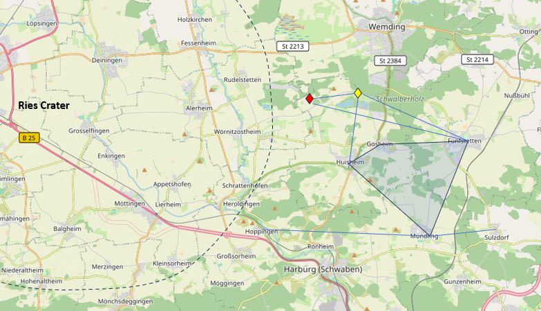
The homeplace, it is a fertile area near an ancient meteorite crater, the Nördlinger Ries. At the high rim of this crater, the Schrödle ancestors have ever been working the land as farmers, millers and craftsman. Surely busy folks familiar with the hardship of essentially self-sufficient life. Places like Fünfstetten, Gosheim, Huisheim, Mündling were the villages of the dwellings, these are very old villages, with records dating back 1200 and more years, but certainly the are in and around the crater has settled since the stone age, many famous old bones have been found.
Two reasons facilitated the new wave of ancestry research: firstly, my father’s family has ever been from this famous spot in Northern Swabia area of nowadays Bavaria, Southern Germany, the old Sualafeldgau dating back to the 8th century AD. Secondly, there are now large numbers of records online available, in particular, the old church records about birth, marriage and death. And, fortunately, these have been well-preserved over the centuries in this area.
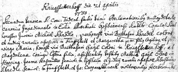
Surely, it is all a matter of patience to find the right records, assign them to the family tree and record the information in a digital format, say, a GEDCOM file. Some, like the marriage record of a son of one of the oldest Schrödle ancestors, a certain Balthasar Schrödle born in the 17th century Fünfstetten, and which is relatively easily read after some practice, and with my training of ancient latin received at school – final I can put that to some use.

Other records are difficult to read – even relatively recent records from the 19th century, because of bad handwriting of some priests, and there lack of attention to readable handwriting.
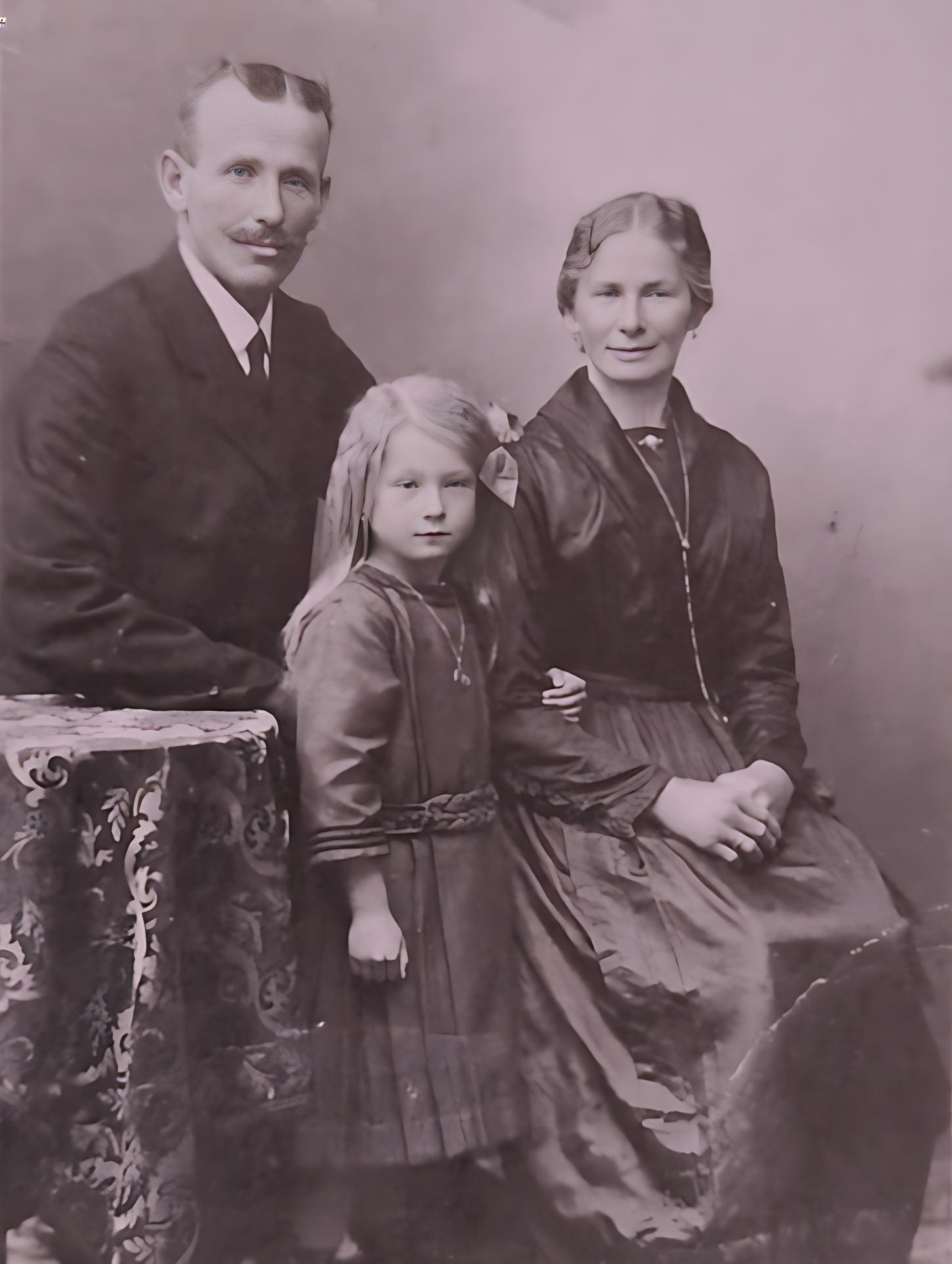
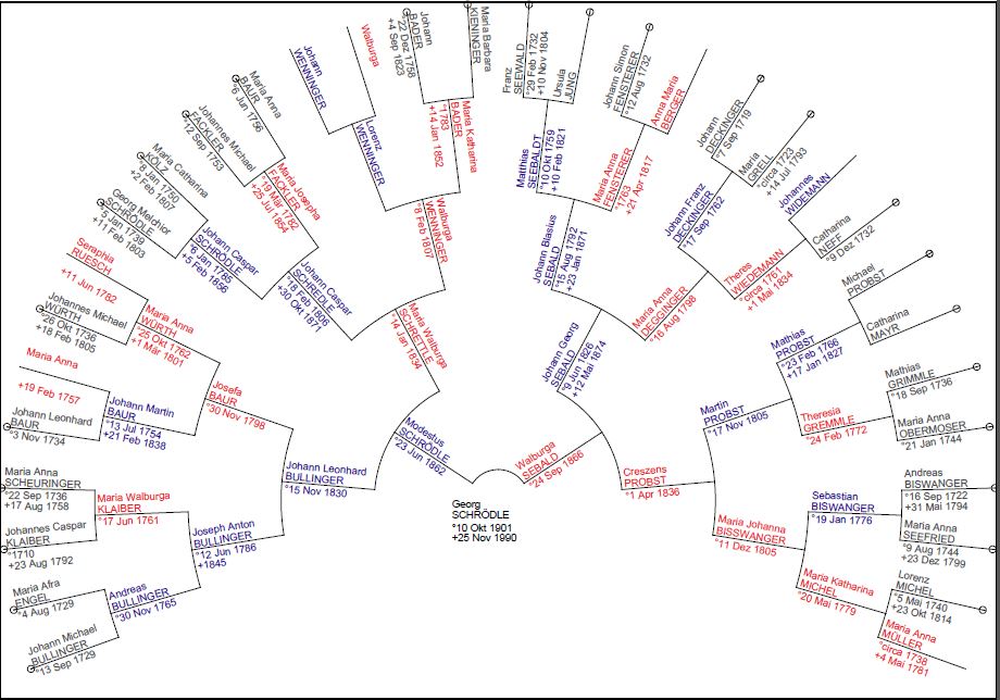
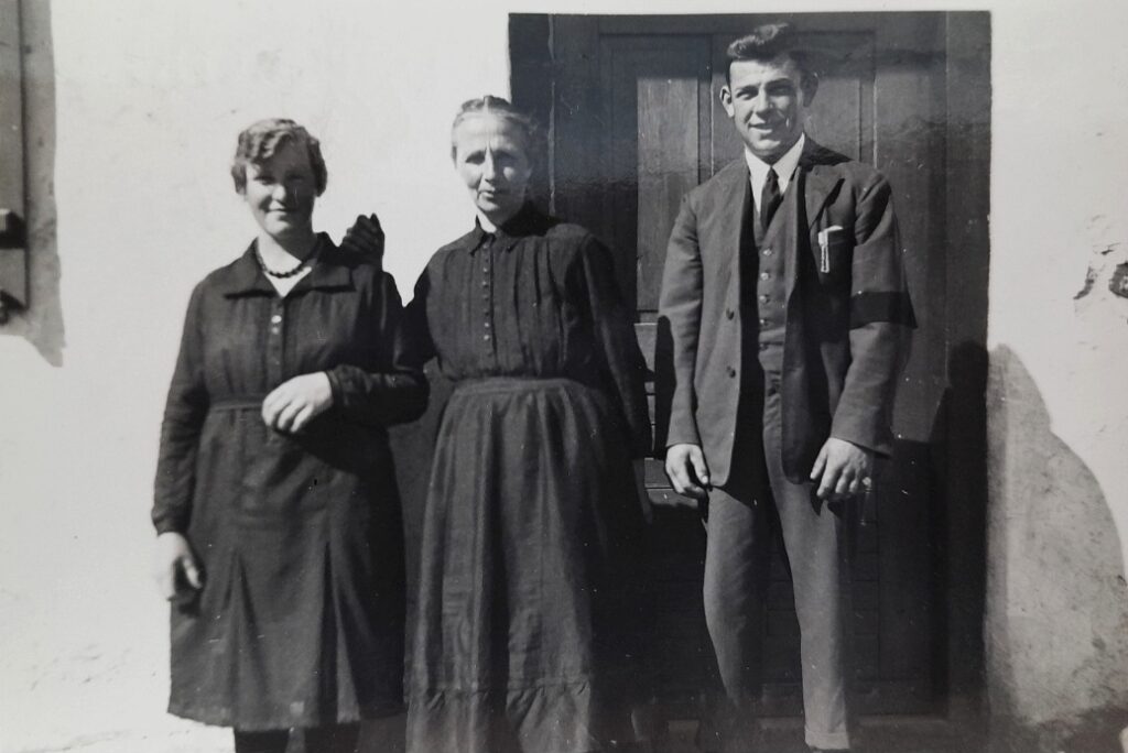
But after all, I have been able to reconstruct the family roots back many generations, here, for my grandfather Georg Schrödle, born in 1901. He was a farmer with patience, a kind man duly respected, still in good memory.
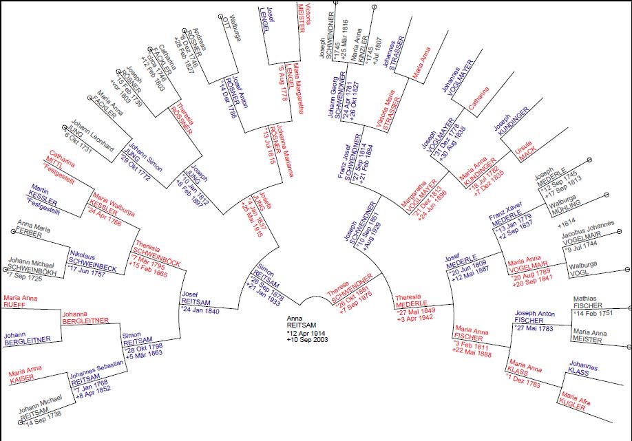
Similarly my grandmother, a descendant of the large Reitsam family in Mündling.
Despite all the wars and difficulties of time, some items including books, papers and photographs still remain in possession of the family, but without knowledge of the ancestry, it is hard to assign these to the right people and to understand how these objects relate to family history. Accordingly, one part of the effort is also to identify all the persons on these old pictures and documents, to avoid this information getting lost over time.
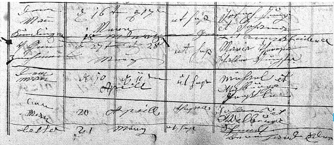
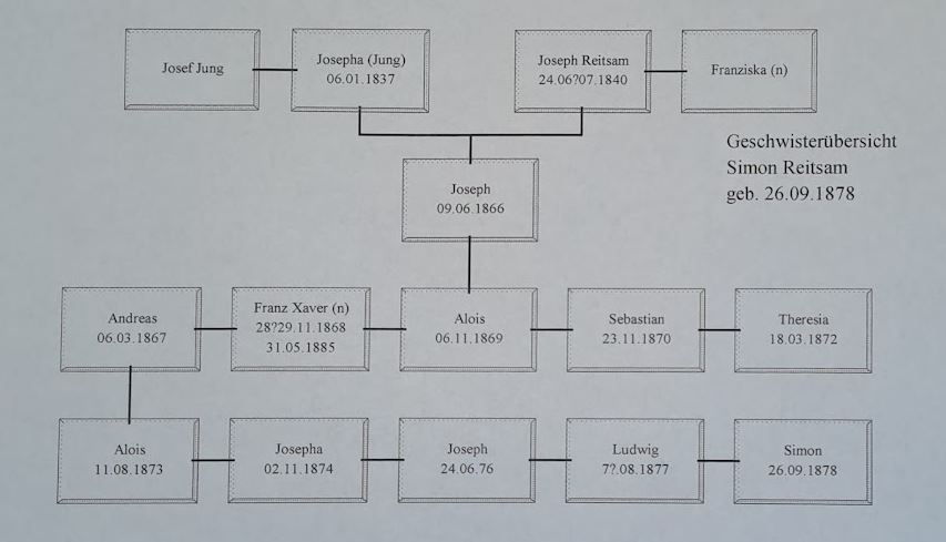
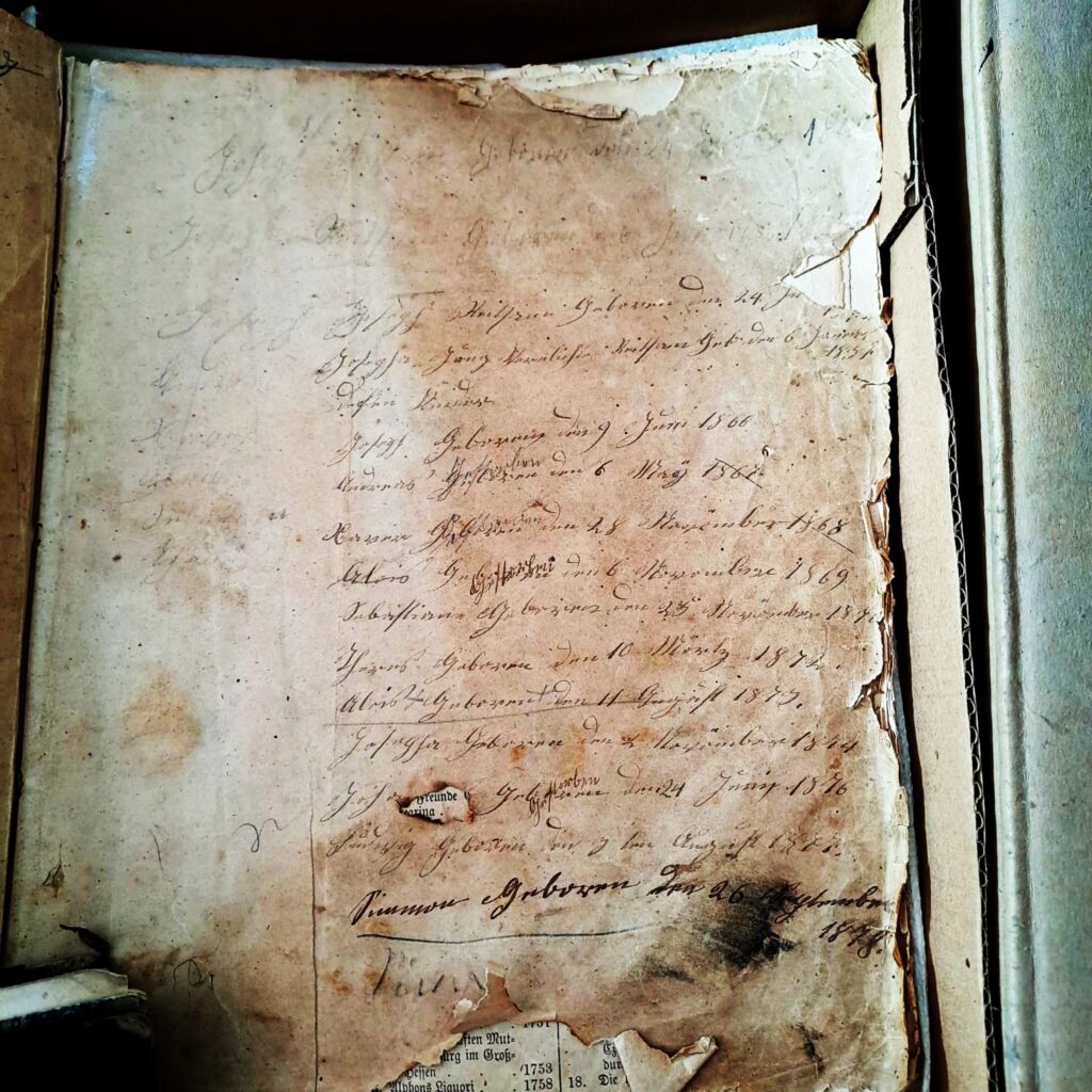
One example is a book, which was in possession of the Reitsam family, the family of my great-great grandparents. While the book itself is nothing of particular value, a history of holy people that was similar to a bible probably the only book in the possession of common people, but with hand-written notes about the family members and birthdays. The last entry, written “Simmon”, is my great-grandfather Simon Reitsam, which which I inherited my first name.
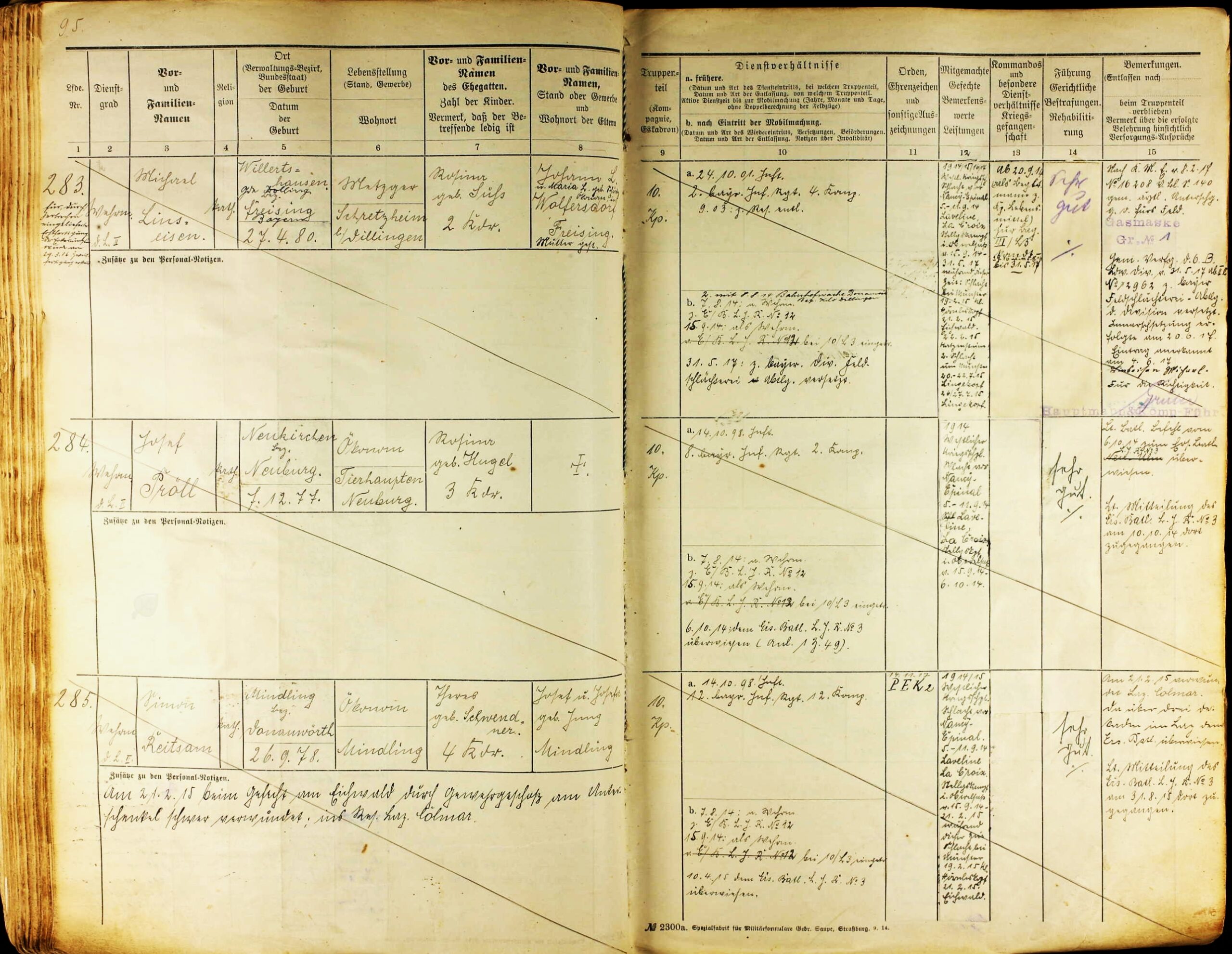
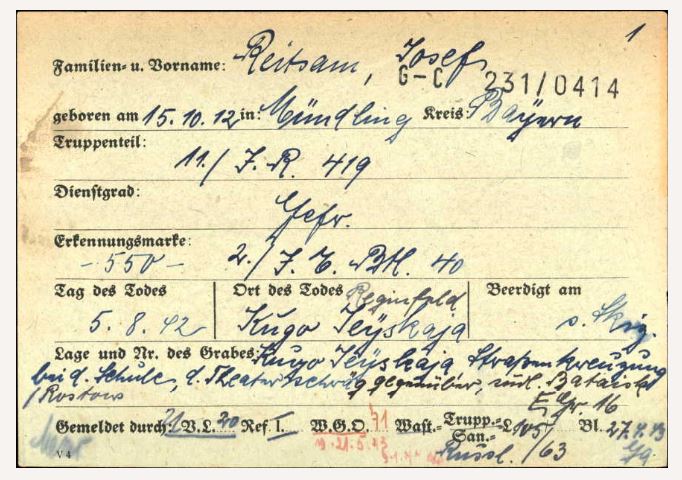
Then, with the proper birthdays and other records, I did further research to find sources in archives, also, military archive collections, and many good records could be found.
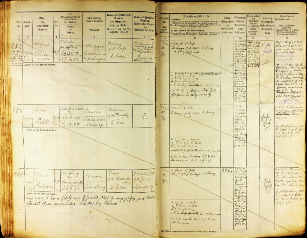
One sad thing of the more recent history is also to number of people lost to wars, for example, Josef Reitsam, my great-uncle (mother of my grandmother, father side).
After all the years and only unclear recollection by hearsay, at least we now know the exact place and circumstances of his tragic and futile death during World War I.
Many other tragic events also came up during the research, which can serve as a warning to the current day: a Schrödle child, drowned in the river feeding the Schrödle grain mill, a Schrödle ancestor, who got pulled into the gears of the mill and died, a Reitsam ancestor, a carpentor and builder, who got hit by a tree and died, many children of the old families that died of infections diseases, and so on. We can hardly imagine all the hardship of the old days, and maybe get a better appreciation of modern times and the value of peace and a society based on the advancement of science of industry. After doing a fair bit of ancestry research now, there is certainly no desire to go back to the “good old times”.
Another, much more pleasurable aspect is the number of “far” relatives, and newly-found parts of the family. There are many relatives living in the US, emigrated to Chicago and similar places. Some still carry the name Schrödle, and actually pretty close relatives. Even in the local area, there are several families, whose relationship to us has been only vaguely known or even completely unknown. If you contact some of these members to find out more about the relationships and ancestors, so far I have encountered only the most helpful and kind people, so this is really a pleasure and joy. Also there are some local historians doing research into certain places and family groups in certain villages. These, too, are the most helpful and kind people encountered.
Some examples, the Reila family related to the great-grandmother, with roots in the Huisheim Angermühle, a grain mill.

The Sebald aunts, daughters of a postman who left the farm villages to follow job opportunities in Augsburg, the largest city in the closer surroundings.
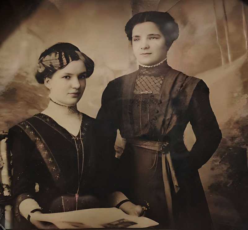
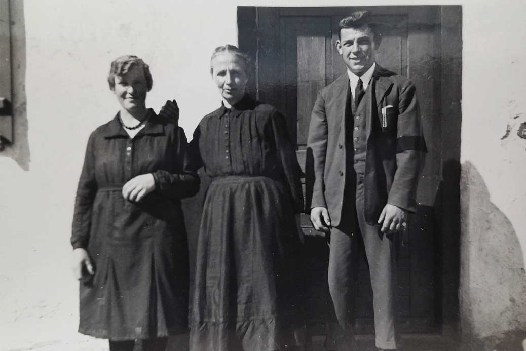
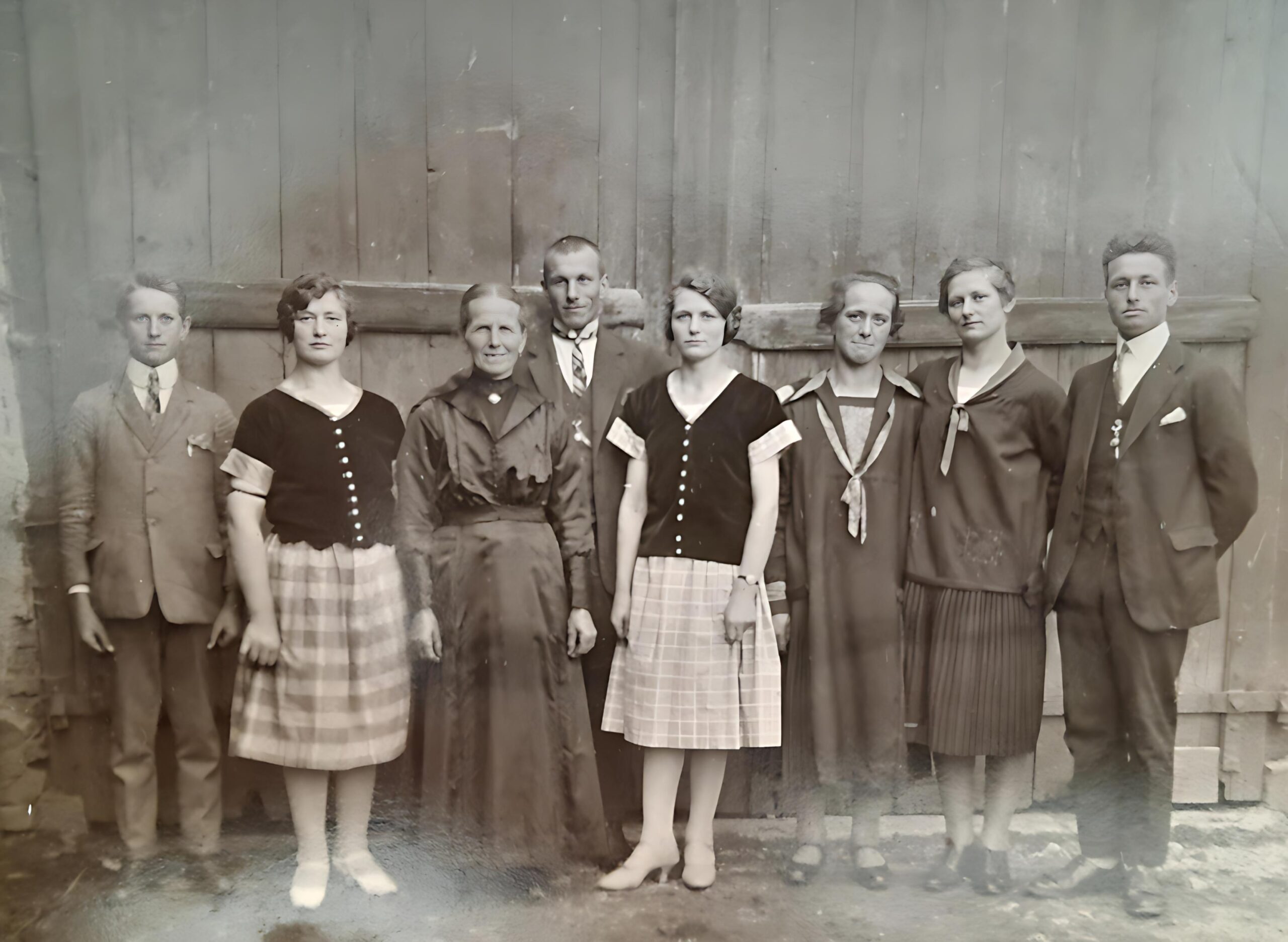
Very unexpected also the huge number of relatives related to my great-grandmother, Therese Schwendner – a kind and distant relative had a picture of here sister will all her children, dating 100 years back.

Let’s see how things will proceed over summer, with less time and more outdoor work to do.